Low budget load cell mod for Logitech G25/G27/G29

Hi,
This mod is something I designed and built based on many things I found on the net.
None was easy enough to make at home with simple tools and common scrap materials.
I went for the cheapest of everything on eBay, but it doesn't mean it's worth less.

I made a few more of these sets for sale if anyone is interested in pre-assembled and tested pieces of handcrafted products. :)
 
I'm also using a modded Logitech pedal (see this post) with load cells from a bathroom scale. In my case the load cells were not riveted but bolted to their plastic feet and the metal part is completely flat. I made a spacer and support out of flat aluminum profile and super-glued it together.

As for spring replacements I found that all solid rubber elements I tried were far too stiff. What did kind of work was a piece of garden hose with V-shaped cutouts on its side. The problem with that solution was, that the material takes some time to return to its original form, so the feel of the pedal changes somewhat. Currently I am using a stack of disc springs and a sponge to dampen the transition. It's rather stiff but very consistent. I also read a comment from a guy somewhere else who uses a plastic cork and is quite satisfied with it.

Edit: Regarding the range of the load cells: As those scales are usually rated around 150-180 kg (with the four cells in parallel) each of the load cells should be able to take at least 40-45 kg (assuming a slightly uneven distribution of the load). In your arrangement this should translate to roughly 30 kg at the pedal (taking the lever into account). As I normally use my pedals without shoes, that is more than enough for me (currently I have it set to around 10-12 kg for full braking, roughly the same the original brake spring was).
 
Last edited:
Upvote 0
oh, plastic cork sounds like a plan! Just off to open a cheap bottle of vino :)

I updated my model on GitHub and also ordered some 1" diameter springs from a chap on eBay in various strengths and lengths to have a play
 
Upvote 0
@Gerzson - do you have a photo of how you mounted the cells together? I'm curious as to how you orientated them
I don't have a photo but I can explain it. There are not many variations. :)
The 2 cells are faced with the white glued side towards each other. I used a pair of M2,5x16mm bolts and 3 pieces of M2,5 nuts as spacer between the cells.
I used this for a totally different project, Logitech pedals not involved, so I didn't experiment with that part.
 
Upvote 0
Found that the circuit works just as well with a single load cell. Have to construct the other half of the bridge on the circuit board, but that then allows unbalancing the bridge with no-load so the amp can be run in positive gain mode instead.

There are some issues with clearance of the upper section of the pedal case with the load cell holder, so I am going to redesign it with a single cell to help.
 
Upvote 0
Have been really pleased with the performance of a single load cell and some flexible hose, so I have decided to make it the primary focus now. A little more travel would be nice as I currently only have about 20mm, so I have decided to try and replicate the configuration of the original lower part of the piston and re-use the G29 spring. The plan is to allow pre-loading with some M10 thread, nuts and washer. I'll let you know how this goes.


Found a cheap place to create the circuit boards that take an Eagle board file: https://dirtypcbs.com - will take a few days before I get to see what they are like

I think it would probably have been better to buy a new pedal set with all the effort I have spent so far, but this has been a great learning experience.
Building is fun, you can learn a lot from it.
I'm a fan of the "built, not bought" phylosophy.
I found JLCPCB for making circuit boards. I will try it soon. I use EasyEDA, the software recommended by them.
 
Upvote 0
I built that same pedal set for under 100 euro, including laser cutting parts and making bronze bearings.
If I say overpriced, I mean it. Their profit definitely helps pay the bills.
I hear you. Personally the price doesn't bother me too much. I tend to value things on what they are worth to me rather than the value of the materials and time. Would I buy them? Probably not, but only because I am pretty sure they would not make me quicker :)

I'm a fan of the "built, not bought" phylosophy.
Totally agree. Not everyone has the patience or tools for it though! I'm lucky that I have a good friend with a 3D printer otherwise I would probably have struggled to tackle the project in this manner

I found JLCPCB for making circuit boards. I will try it soon. I use EasyEDA, the software recommended by them.
Damn they are cheap! Let me know how you get on.
 
Upvote 0
well, https://dirtypcbs.com came out good! Just 4 weeks from ordering to receiving them in the post. Got 15 boards for $11, which is a bloody bargain

dirtypcb_lc_amp2.jpg

Now waiting for my buddy to return from working abroad so we can print out v3 of the model which re-uses the original spring and rubber block from the G29.
 
Upvote 0
Looking good. I don't quite understand how your panel works exactly. Why do you have an input for clutch, and not for throttle?
Does this circuit do inverting too? Mine has only one trimmer pot, yours has 3. Are those necessary? What do they do?
 
Upvote 0
Hi @Gerzon - some of the components are optional as the board allows using 1 or 2 load cells. Only two pots are required for either configuration. In both configurations it inverts the signal, but the inversion is done differently for each. I was just mucking around with ideas and decided to make one board to handle both.

For either configuration you still install R_GAIN.

For one LoadCell you use R_BAL1 and also populate R1 and R2 as the other half of the wheatstone bridge. R_BAL1 is then used to unbalance the bridge so that the load cell will re-balance the bridge (i.e. applying load will cause the voltage difference to approach 0mv and effectively invert the signal). R_REF is just tied to GND in this configuration.

For two load cells you populate R_GAIN and R_REF. This then requires the load cells to be connected in reverse so that the +Vin is the lower voltage from the bridge and -Vin the higher. By adjusting R_REF so that the voltage applied is 3.1v this allows the amplifier to invert the gain and drop the voltage when load is applied.

The clutch is just another bit of a hack due to my setup. My rig restricts comfortable access to the middle pedal due to the wheel being mounted on a single central post, so I removed the clutch and put the brake over to the left. Leaving the clutch connections open caused the wheel to glitch, so I found I needed to simulate the pot which is the job of R3 and R4 on the board (I could have just re-installed the clutch in the brake slot, but it put strain on the wiring loom that I was not happy with).

I have some more details on my github page: https://github.com/GeekyDeaks/g29-load-cell
 
Upvote 0
Do you have your circuit schematic to hand @Gerzson ? I'm interested to see if you got it to invert with only one pot. I guess you could tie ref to V+, but the lack of adjustment on a PS4 was a limiting factor for me
 
Upvote 0
Do you have your circuit schematic to hand @Gerzson ? I'm interested to see if you got it to invert with only one pot. I guess you could tie ref to V+, but the lack of adjustment on a PS4 was a limiting factor for me
Mine is simple as it gets. I use only the gain pot and the signal voltage is decreasing with pressure applied. I play on PC only, so inversion is not an issue for me.

I see you put a lot of thought into it. One board for multiple variations.

My PCB order from JLCPCB (for a different project) arrived in 2 weeks. I got an extra discount for first order after registration. My 5 panels cost only $1.80 with shipping. Unbeatable price. :D
 
Upvote 0
I have some more details on my github page: https://github.com/GeekyDeaks/g29-load-cell
Hi GeekyDeaks,
nice project! I am planning to build this for my G29. Parts are on the way :) .
But I have two questions, your github page does not answer (as far as I see it).
1. which settings do you use, when printing the STL? How much infill (percentage) do you suggest?
2. you mention that you attached a pdf of the PCB containing the measures. But there are no measurements nor any hint for the size. Am I wrong?

It would be really nice, if you could add this information to the github page.

Another question: Why did you drop the idea of the double Load cell approach?

Thanks in advance. And again: really nice project! :thumbsup:
 
Upvote 0
Hi @BD992000 !

I have asked my friend for the infill he used. I'll let you know and update the project page once I have the info.

The size for the DIY PCB is not very clear, sorry! What I should have said is that the PDF has the correct size image, so if you print it out 100% scale you should be good. I actually have a bunch of PCBs spare, if you want me to post one to you? I got about 15 from dirtypcbs.com for $11 including postage

I dropped the dual cell approach because it didn't really offer any benefit. I mistakenly thought it would double the load range, but they need to be in parallel to achieve that. It does still offer twice the voltage difference under load, but it doesn't seem to make a noticeable difference to the resolution. The model now fits into the case too and the cell is unlikely to drop out if you invert the pedals.

The only thing I would point out about the design is that the pedal feels more like a road car than a race car. i.e. it's not super hard. This is great for me as I race in my socks, but you might want to replace the rubber block with something a little firmer if you prefer a less squishy feel :)

I need to also update the project on the procedure to calibrate the trim pots as it's easy to get lost because tweaking one affects the other
 
Upvote 0
I dropped the dual cell approach because it didn't really offer any benefit.
You don't have to read this. I warn you! ;)

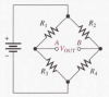
To my knowledge, dual cell setup can increase sensitivity. This Wheatstone bridge is a setup with two 1k ohm 'resistors', one been almost stable and the other subject to tension and compression (they are equal components but with different placements in the material itself). This is done to prevent temperature induced variations (temparature does change pressure and compression state of the materials) and the cell will read it!

Take the attached image. With just one cell, it can take the place of R2-R4 or R1-R3. It's indifferent.
Suppose we choose R2-R4, and R2 is the variable element (R4 stays stable with pedal pressure).

Points A and B and at equal potential without pedal pressure. Sensor output will be zero.
As soon as you apply pressure, R2 changes making a difference between point A and B. That's what you measure. Sensor output will not be zero. The electronis are just an amplifier (in fact, a differencial amplifier).

Now, suppose dual cell setup. This second cell will take the place of R1-R3.
In this case, you want to have R3 as variable resistor, not R4, or else theycancel each other.
This way, while R2 is, let's suppose, pulling point B up, R3 will be pulling point A down. The difference between A and B will be double, hence more sensitivity.
The advantage of this setup is you already have the four resistor to make the Wheatstone bridge (with one cell, you should have two normal resistors to complete the configuration).

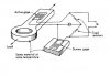
Is all that necessary? I suppose not. You can increase sensitivity by just making the cell thinner (take of some material from the region below the white thing (on the down side). It will bend more => more output from the same pressure.
 

Attachments

  • Wheatstone Bridge.png
    Wheatstone Bridge.png
    49.1 KB · Views: 177
  • Material.jpg
    Material.jpg
    25.6 KB · Views: 137
Upvote 0
Haha! Thanks for the detailed response. TBH I have learnt an awful lot about Wheatstone bridges over the past month or so!

I tried to summarise what you are alluding to above in the previous sentence:

It does still offer twice the voltage difference under load, but it doesn't seem to make a noticeable difference to the resolution.

With just a single cell, whilst the voltage difference is half that with two cells, you can simply double the amplification and, at least with my foot, I could not tell the difference between the two. I was concerned about noise with the higher amplification, but I could not see any noticeable increasing in the fluttering of the output.

EDIT: there is also some mechanical complexity to be aware of with two cells, since the entire assembly needs to be able to move very slightly.

Does this address your concern?
 
Upvote 0

Latest News

Are you buying car setups?

  • Yes

  • No


Results are only viewable after voting.
Back
Top