First step for making the 2-way lines is checking out the road and surfaces.ini for impending problems with the side lines. One way for that is to load the track with some layout that already has AI lines and have a look at those. May require disabling of "Origin shift" in CSP settings > "Graphic adjustments". If the red sides follow exactly the border between the asphalt and the green or brown stuff then most probably you will have the same side lines automatically generated from the game after your attempt.

Another way of checking is to confirm the names of the objects that are physics. Those have number for first symbol in the names (0 doesn't count). 1ROAD next to 1SAND when the surface "SAND" has "IS_VALID_TRACK=0" tag in "..\AssettoCorsa\system\data\surfaces.ini" or in the layout's "surfaces.ini" means the side line will be created on that border.


When the objects for physics are correct you need to prepare the new layout's structure. In Windows Explorer open the track's folder (fastest way - right-click or use the three dots next to the track's name in Content Manager). In there create new folder (i.e. "2way") and while empty - copy that into "ui". Then from "ui" or some of the other track's layouts select and copy the three .png and the "ui_track.json" into the empty "..ui\2way\" folder. Edit the contents of "ui_track.json" to reflect the changes in this layout. Avoid putting the new name entirely different than the other names of the track's layouts but add few words after the old name. When done editing that re-open CM and see if the new layout shows up for selecting.


Then proceed to creating the file structure - copy the "data" folder and map.png from some of the existing layouts and paste those into "..\<track name>\2way\". Make a copy from some of the other "models_***.ini" for that track or if there are none you need to create new in the track's folder ("..\<track name>\") and name it "models_2way.ini" to match the name of the layout's folder. If you are making new - open it and create a paragraph
[MODEL_0]
FILE=euphoria_hillside_park.kn5 ;the actual name of the kn5 model in the track's folder;
POSITION=0,0,0
ROTATION=0,0,0

After that load the new traffic layout in "Practice" mode. When all of the necessary models are present the car will be functioning and positioned correctly and you will be ready for drawing the fast_lane. Notes on the car choice - large cars with longer wheelbase are more stable but the lines drawn with those have longer segments and in tight turns that sometimes becomes too obvious later with the AI cars. Drawing the line at racing pace is not necessary and two lines drawn with different cars at different pace work the same provided the lines have the same geometry. So choose a car that has small enough turning circle, smooth and broad torque band, big enough suspension travel and gripping tires to give you the best traction and stability and then drive it like a grownup. Choosing a car with weak engine allows for relaxing your feet by flooring it for long enough during the drive and that matters a lot when it takes more than 1 hour for driving the line on a long road.
Next on the list - choosing the actual route. The simpler - the better. Avoid as much as possible: overlapping the line by driving again in the same lane; crossing the paths of the AI; narrow passages between walls or near obstacles.
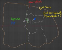
Find the best places for the U-turns with road tagged as "IS_VALID_TRACK=1" wide enough to accommodate the turning circle of most cars in the "street" class. On a long road or large road grid use the "map.png" file to actually draw into it the arrows to guide you where to turn and color-code those if it's multi-lane and you need to make another parallel loop. So your first stab at making the traffic is a drawing over the "map.png" and then practice run on which you confirm on track where and how to turn.
Settings of CSP and other for the time of driving the new lines - the entire "New AI behavior" module should be turned off, "Origin shift" in CSP settings > "Graphic adjustments" should be disabled. Deactivate all Python apps except Sol controls.
When all of the above is done and you feel there's enough energy left for the long haul - start the engine. By that I mean choose the starting point of the line on some straight bit with distinct object next to the side which you take as reference. YOU NEED TO STOP THE RECORDING AT THE END OF THE DRIVE JUST BEFORE YOU REACH THE STARTING POINT. This method doesn't need the first timing gate to form a "start line" and to begin and close the recording there. I use "start pits" to record the line from anywhere I fancy to anywhere I decide to stop.

On multi-lane traffic it simply is the only way for creating the parallel lines. On A2B hill-climbs it's the easiest way to make the AI cross the finish line. The drawback - after completing the drive and renaming the "pit_lane.ai.candidate" to "fast_lane.ai" the game takes it's time to evaluate it upon loading which takes as long as the time to actually render the line upon exiting the session. So if the rendering needs 2 hours it will take twice that when making the line from "pit_lane.ai.candidate" and you need to interact in the middle of that wait. In conclusion - to save time you may consider the option to start the 2-way just before the timing gate as long as you don't need to pass through it again in the same direction for making another round. In that case using the standard "start recording" in the "AI" app will spare you the wait for loading the raw line and the rendering will be done upon exit of the same session. To see the location of the timing gate you have no other option but to use 3DSimED to load the relevant track's models prior to the attempt.

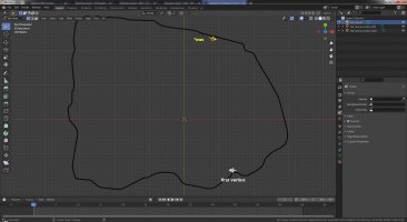
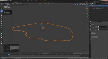
*To make things more interesting the author in this example had the track encrypted and for that the wire-frame view is necessary. The positioning of these two gate objects would prevent making of the traffic that I've done using the "start pits".
The timing gate may not be on the map, may not be in the place that the map says it will be, or it may not be present at all. If any of this and without checking - you will waste a lot of time blindly driving around just to find out that timing doesn't work and the recording of the traffic you want is never going to happen. In case you need the gate to be somewhere else or if it simply is missing in the track you can create it by placing by the sides of the road two primitives in 3DSimED. Boxes with 1m sides are fine and the names should be "AC_TIME_0_L" and "AC_TIME_0_R" for the left and right side respectively. "Plugin Export" that as "gate.kn5" and make it load by adding a paragraph into "models_2way.ini". Now, if the track already has those objects there is a big difference whether you put the new "gate.kn5" model last in the queue or first. Put it before all others as [MODEL_0] to make it work and observe the proper sequential numbering of the next models.
But if you are like me and want to get straight to it - use the "start pits" and just drive the route that you want. Just remember the place of the start and on the second approach to it click "recording" to stop the process before you reach the starting point. After exiting that session you will find a single "pit_lane.ai.candidate" in "..\<track name>\2way\ai\" folder.

Rename it to "fast_lane.ai" and load another "Practice" session. This time loading will be slowed down by the raw line that you want to render. Be patient and don't terminate "acs.exe". If you like to have the PC available for other tasks use "Alt+Tab" or "Ctrl+Alt+Del" to make the "Desktop Manager" of Windows re-gain control over the screen.
After the loading is complete you need to use "start pits" again and depending if you intend to actually use the "pit_lane.ai" or a duplicate of the "fast_lane.ai" you may want to drive the good short guiding line into and out of the pits. When that is done click "recording" to stop the process and exit the session. That's when the actual usable lines are made by the game. The good result is two new .candidate files which need to be renamed by removing the ".candidate' from the names. The initial "fast_lane.ai" needs to get out of the way and for safekeeping you may pack it into a zip.
There are two scenarios for "pit_lane.ai": 1. using the short line that only covers the pit area or 2. making a copy of "fast_lane.ai" and renaming that copy to "pit_lane.ai". That gives the opportunity to scatter the pits along the route and make the AI join more naturally for a street driving. But when you have all cars starting from the pits using the duplicate "fast_lane" has no benefits.
If you think that's all - it's not. For most of the AI to work with the line there has to be some track-specific hints. A simple template for creating such "..\content\tracks\<track name>\2way\data\ai_hints.ini" file is
[HINT_0]
START=0.001
END=0.999
VALUE=0.8
[BRAKEHINT_0]
START=0.001
END=0.999
VALUE=0.9
[MAXSPEED_0]
START=0.001
END=0.999
VALUE=160
[DANGER_0]
START=0.001
END=0.999
LEFT=0.6
RIGHT=0.6
From those paragraphs most likely [HINT_**] and [MAXSPEED_**] would be of use, the first telling the AI that each corner radius is shorter than the look-ahead estimate (i.e. factor of 0.8) and the second - not to exceed the defined speed. Hints can work in combination and be multiple of the same kind. The numbering is [HINT_0], [HINT_1], [HINT_2], etc. and the "START=***" and "END=***" determine the points on the spline in form of percentage length from the starting point. It is displayed on the "AI" app but with a long splines you might want to use the "DRS zones" app instead to avoid CPU overload.

The way I find most effective for tuning the hints is to load a well-developed car in "Hotlap" mode and enable the AI (Ctrl+G and Ctrl+C) so I can watch and listen for problems. If the AI resembles human driver then that part of the course is ok. If not I take note of the positions and edit the hints. Testing of the line is not complete without a Track day with AI flood. Before judging that some line is good or bad consider this: some AI cars experience difficulties with new AI flood when spawned at speed in the highest gear and have to downshift fast without any hesitation. Instead of doing it as expected many AI just can't engage the clutch. Here's what solves this issue: unpacking of car's data and enabling the unpacked data as default by renaming "data.acd" to "data.acd1", then edit of "drivetrain.ini" to have [AUTOCLUTCH]
MIN_RPM=100
Provided there's no other problems with the car's physics that makes it go without a hiccup. Additional benefit of using the unpacked data is the option to train that AI better so it doesn't hit the walls due to cutting corners or missing the turn.
Not essential but nice to have are F3 track-side cameras. The positions and directions of those are tied to the spline length and you can't simply use the old "cameras.ini" from another layout. For making the F3 cams I'm using the "Custom Shaders Patch debug app Advanced"
Again by enabling AI and setting [MAXSPEED_0] low enough I'm able to go round the course and in one lap to position all the cameras so the cars remain in frame later on. For making the cams I usually let AI drive some wide car with less body roll - like a Hummer in case of wide roads, so with F5 and some rotation I can reach over or near the edge of the road. Thanks to LeBluem aka @Please Stop This for making the useful tool.
Additional note on the cams - since v0.99k the app offers "new auto cams" mode of recording and it works very well for making huge sets for long lines when some conditions are met: the timing gate "0" should be present and at the exact spot where the line begins, you set "min_z=0" and "max_z=1", in CSP settings disable "New AI behavior" module and disable "Use double precision physics", in "Hotlap" or "Track day" session position the cams by selecting F5 and looking at the rear quarter close to the road edge without going into some buildings and other obstructions, at height of more than 2 m above ground. To add variety to the set you can change the "IN" and "OUT" while the AI does the driving. For wide and long straight roads - bigger distances between cams, for narrows and twisties - shorter distances. If the AI speed is limited that also calls for shortening the "IN" and "OUT". If "IN" is bigger than "OUT" cams show more the front of the cars approaching, if "OUT" is bigger - more of the rears is in the shots.
Let me know if splitting the opposite lanes is interesting for you and I will add more info. And don't hold back if you see the results of the attempts exceed your expectations - share the layouts with us!
Another way of checking is to confirm the names of the objects that are physics. Those have number for first symbol in the names (0 doesn't count). 1ROAD next to 1SAND when the surface "SAND" has "IS_VALID_TRACK=0" tag in "..\AssettoCorsa\system\data\surfaces.ini" or in the layout's "surfaces.ini" means the side line will be created on that border.
When the objects for physics are correct you need to prepare the new layout's structure. In Windows Explorer open the track's folder (fastest way - right-click or use the three dots next to the track's name in Content Manager). In there create new folder (i.e. "2way") and while empty - copy that into "ui". Then from "ui" or some of the other track's layouts select and copy the three .png and the "ui_track.json" into the empty "..ui\2way\" folder. Edit the contents of "ui_track.json" to reflect the changes in this layout. Avoid putting the new name entirely different than the other names of the track's layouts but add few words after the old name. When done editing that re-open CM and see if the new layout shows up for selecting.
Then proceed to creating the file structure - copy the "data" folder and map.png from some of the existing layouts and paste those into "..\<track name>\2way\". Make a copy from some of the other "models_***.ini" for that track or if there are none you need to create new in the track's folder ("..\<track name>\") and name it "models_2way.ini" to match the name of the layout's folder. If you are making new - open it and create a paragraph
[MODEL_0]
FILE=euphoria_hillside_park.kn5 ;the actual name of the kn5 model in the track's folder;
POSITION=0,0,0
ROTATION=0,0,0
After that load the new traffic layout in "Practice" mode. When all of the necessary models are present the car will be functioning and positioned correctly and you will be ready for drawing the fast_lane. Notes on the car choice - large cars with longer wheelbase are more stable but the lines drawn with those have longer segments and in tight turns that sometimes becomes too obvious later with the AI cars. Drawing the line at racing pace is not necessary and two lines drawn with different cars at different pace work the same provided the lines have the same geometry. So choose a car that has small enough turning circle, smooth and broad torque band, big enough suspension travel and gripping tires to give you the best traction and stability and then drive it like a grownup. Choosing a car with weak engine allows for relaxing your feet by flooring it for long enough during the drive and that matters a lot when it takes more than 1 hour for driving the line on a long road.
Next on the list - choosing the actual route. The simpler - the better. Avoid as much as possible: overlapping the line by driving again in the same lane; crossing the paths of the AI; narrow passages between walls or near obstacles.
Find the best places for the U-turns with road tagged as "IS_VALID_TRACK=1" wide enough to accommodate the turning circle of most cars in the "street" class. On a long road or large road grid use the "map.png" file to actually draw into it the arrows to guide you where to turn and color-code those if it's multi-lane and you need to make another parallel loop. So your first stab at making the traffic is a drawing over the "map.png" and then practice run on which you confirm on track where and how to turn.
Settings of CSP and other for the time of driving the new lines - the entire "New AI behavior" module should be turned off, "Origin shift" in CSP settings > "Graphic adjustments" should be disabled. Deactivate all Python apps except Sol controls.
When all of the above is done and you feel there's enough energy left for the long haul - start the engine. By that I mean choose the starting point of the line on some straight bit with distinct object next to the side which you take as reference. YOU NEED TO STOP THE RECORDING AT THE END OF THE DRIVE JUST BEFORE YOU REACH THE STARTING POINT. This method doesn't need the first timing gate to form a "start line" and to begin and close the recording there. I use "start pits" to record the line from anywhere I fancy to anywhere I decide to stop.
On multi-lane traffic it simply is the only way for creating the parallel lines. On A2B hill-climbs it's the easiest way to make the AI cross the finish line. The drawback - after completing the drive and renaming the "pit_lane.ai.candidate" to "fast_lane.ai" the game takes it's time to evaluate it upon loading which takes as long as the time to actually render the line upon exiting the session. So if the rendering needs 2 hours it will take twice that when making the line from "pit_lane.ai.candidate" and you need to interact in the middle of that wait. In conclusion - to save time you may consider the option to start the 2-way just before the timing gate as long as you don't need to pass through it again in the same direction for making another round. In that case using the standard "start recording" in the "AI" app will spare you the wait for loading the raw line and the rendering will be done upon exit of the same session. To see the location of the timing gate you have no other option but to use 3DSimED to load the relevant track's models prior to the attempt.
*To make things more interesting the author in this example had the track encrypted and for that the wire-frame view is necessary. The positioning of these two gate objects would prevent making of the traffic that I've done using the "start pits".
The timing gate may not be on the map, may not be in the place that the map says it will be, or it may not be present at all. If any of this and without checking - you will waste a lot of time blindly driving around just to find out that timing doesn't work and the recording of the traffic you want is never going to happen. In case you need the gate to be somewhere else or if it simply is missing in the track you can create it by placing by the sides of the road two primitives in 3DSimED. Boxes with 1m sides are fine and the names should be "AC_TIME_0_L" and "AC_TIME_0_R" for the left and right side respectively. "Plugin Export" that as "gate.kn5" and make it load by adding a paragraph into "models_2way.ini". Now, if the track already has those objects there is a big difference whether you put the new "gate.kn5" model last in the queue or first. Put it before all others as [MODEL_0] to make it work and observe the proper sequential numbering of the next models.
But if you are like me and want to get straight to it - use the "start pits" and just drive the route that you want. Just remember the place of the start and on the second approach to it click "recording" to stop the process before you reach the starting point. After exiting that session you will find a single "pit_lane.ai.candidate" in "..\<track name>\2way\ai\" folder.
Rename it to "fast_lane.ai" and load another "Practice" session. This time loading will be slowed down by the raw line that you want to render. Be patient and don't terminate "acs.exe". If you like to have the PC available for other tasks use "Alt+Tab" or "Ctrl+Alt+Del" to make the "Desktop Manager" of Windows re-gain control over the screen.
After the loading is complete you need to use "start pits" again and depending if you intend to actually use the "pit_lane.ai" or a duplicate of the "fast_lane.ai" you may want to drive the good short guiding line into and out of the pits. When that is done click "recording" to stop the process and exit the session. That's when the actual usable lines are made by the game. The good result is two new .candidate files which need to be renamed by removing the ".candidate' from the names. The initial "fast_lane.ai" needs to get out of the way and for safekeeping you may pack it into a zip.
There are two scenarios for "pit_lane.ai": 1. using the short line that only covers the pit area or 2. making a copy of "fast_lane.ai" and renaming that copy to "pit_lane.ai". That gives the opportunity to scatter the pits along the route and make the AI join more naturally for a street driving. But when you have all cars starting from the pits using the duplicate "fast_lane" has no benefits.
If you think that's all - it's not. For most of the AI to work with the line there has to be some track-specific hints. A simple template for creating such "..\content\tracks\<track name>\2way\data\ai_hints.ini" file is
[HINT_0]
START=0.001
END=0.999
VALUE=0.8
[BRAKEHINT_0]
START=0.001
END=0.999
VALUE=0.9
[MAXSPEED_0]
START=0.001
END=0.999
VALUE=160
[DANGER_0]
START=0.001
END=0.999
LEFT=0.6
RIGHT=0.6
From those paragraphs most likely [HINT_**] and [MAXSPEED_**] would be of use, the first telling the AI that each corner radius is shorter than the look-ahead estimate (i.e. factor of 0.8) and the second - not to exceed the defined speed. Hints can work in combination and be multiple of the same kind. The numbering is [HINT_0], [HINT_1], [HINT_2], etc. and the "START=***" and "END=***" determine the points on the spline in form of percentage length from the starting point. It is displayed on the "AI" app but with a long splines you might want to use the "DRS zones" app instead to avoid CPU overload.
The way I find most effective for tuning the hints is to load a well-developed car in "Hotlap" mode and enable the AI (Ctrl+G and Ctrl+C) so I can watch and listen for problems. If the AI resembles human driver then that part of the course is ok. If not I take note of the positions and edit the hints. Testing of the line is not complete without a Track day with AI flood. Before judging that some line is good or bad consider this: some AI cars experience difficulties with new AI flood when spawned at speed in the highest gear and have to downshift fast without any hesitation. Instead of doing it as expected many AI just can't engage the clutch. Here's what solves this issue: unpacking of car's data and enabling the unpacked data as default by renaming "data.acd" to "data.acd1", then edit of "drivetrain.ini" to have [AUTOCLUTCH]
MIN_RPM=100
Provided there's no other problems with the car's physics that makes it go without a hiccup. Additional benefit of using the unpacked data is the option to train that AI better so it doesn't hit the walls due to cutting corners or missing the turn.
Not essential but nice to have are F3 track-side cameras. The positions and directions of those are tied to the spline length and you can't simply use the old "cameras.ini" from another layout. For making the F3 cams I'm using the "Custom Shaders Patch debug app Advanced"
Again by enabling AI and setting [MAXSPEED_0] low enough I'm able to go round the course and in one lap to position all the cameras so the cars remain in frame later on. For making the cams I usually let AI drive some wide car with less body roll - like a Hummer in case of wide roads, so with F5 and some rotation I can reach over or near the edge of the road. Thanks to LeBluem aka @Please Stop This for making the useful tool.
Additional note on the cams - since v0.99k the app offers "new auto cams" mode of recording and it works very well for making huge sets for long lines when some conditions are met: the timing gate "0" should be present and at the exact spot where the line begins, you set "min_z=0" and "max_z=1", in CSP settings disable "New AI behavior" module and disable "Use double precision physics", in "Hotlap" or "Track day" session position the cams by selecting F5 and looking at the rear quarter close to the road edge without going into some buildings and other obstructions, at height of more than 2 m above ground. To add variety to the set you can change the "IN" and "OUT" while the AI does the driving. For wide and long straight roads - bigger distances between cams, for narrows and twisties - shorter distances. If the AI speed is limited that also calls for shortening the "IN" and "OUT". If "IN" is bigger than "OUT" cams show more the front of the cars approaching, if "OUT" is bigger - more of the rears is in the shots.
Let me know if splitting the opposite lanes is interesting for you and I will add more info. And don't hold back if you see the results of the attempts exceed your expectations - share the layouts with us!
Last edited: