Mobile Driving/Flying Cockpit with Motion and Tactile ( Build )

In a very rare event, the print failed, so I got coal for Christmas this morning :(
I have "Err: EXTR. FAN ERROR" so I'll probably need a replacement part before I can continue printing.
Edit: Fixed it! There was just a piece of filament stuck in the fan.

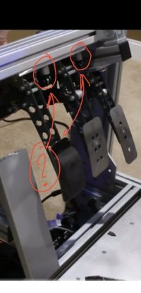
Two things you can see in this picture.
  1. There is now access to one of the two detent stops under the throttle where the aluminum version covered these.
  2. The fit is right on.
The 40x40 profile fit is a bit too "perfect". I'm concerned that by the time all 60mm of depth around the profile are printed that there could be just enough layer line drift to make putting the profile in something requiring a hammer. So before I print this again, I'm going to add just a bit more space.
In addition I've added a hole so I can reach the second of the detent stop holes in the bottom of the throttle case.

ThrottleMountPartialPrint_6505.jpg


This gives you an idea how close the fitting is. The profile pushed in with almost no effort after I perfectly aligned it, but it managing to hold the weight of the throttle with only 10mm of depth and no fasteners.

solidfitting_6506.jpg


Here is the new version with 0.3mm tolerance around the 40x40 profile and with the new access hole.
AccessPort.jpg


I had never used this feature before, but having the spool weight included in the filament used weight is great! I just measured a spool and it looks like I have about 150g of filament to spare :)
Otherwise, I thought it was enough, but wasn't sure.

SpoolWeight.jpg
 
Last edited:
Wow! It appears that the filament snapped mid print.

2nd Print failure on this one. For some reason I like Jet Black for mounts like this, so I ordered a couple more rolls.

In the over engineered category, this mount feels completely solid with only 2 bolts in place and only 20mm of the 60mm profile support collar in place, so I think I'll use it as is while I wait for more filament to arrive.

DCS content is on sale right now, and I picked up a few new aircraft for it.
ThrottleMount_6510.jpg
 
Last edited:
I'm exploring the idea of using a magswitch as part of a quick release mechanism. This would require having a piece of steel captured, possibly just bolted to profile. The downside is that steel will rust and even if I prime/paint it, bolts will likely scrape the coating off and where the magnet touches down will wear. I'm also not setup well to handle steel in my shop. Aluminum is much easier for wood working tools.

I think a thin 3D printed layer to fit between the steel and the profile and extending up around the edges of the steel plate might be a good idea.

I have a number of magswitch guides, and fences in my shop and they work very well on my table saw and band saw tables which are steel and require cleaning and coating to keep rust free.

Magswitch includes STEP files of their switches so I can very easily create 3D printed fittings for them and I'm not worried about PLA under compression.

This is just a doodle. There isn't enough clearance under the seat for this to fit, but it's an idea. For a switch like this the part needs to be constrained and supported on all key load axis and the magnet would just hold it in place on an axis that doesn't get much torque applied to it.

MagswitchIdea.jpg
 
Last edited:
This might actually work....

I just ordered some cold rolled steel 1.25" x 1/4" thick that I can simply cut to length, drill, and bevel along with a pair of 95lb Magswitches to see if this will work. I'm thinking I'll use simple rustoleum primer on the back of the steel and I'll just use the same coating I use on my table saw table on the outer facing part of the plate.

MagReleasePotential.jpg
 
Last edited:
BTW I did shoot some video for my first "Your Custom Simrig" episode. I kept coming up with things to add and now I've got at least the next 3 episodes semi-outlined.
 
Last edited:
This is a 10 degree wedge for the clutch. It appears that it is enough to keep the ball of my foot from bending backwards uncomfortably(never an issue for floor mounted clutches), but I need the new pedals faces on Thursday before I can be sure this is right. I may move the clutch hole backwards a bit too, but not until I see how it feels with the new pedal faces.

Edit: 4/13 Printing a 15 degree wedge and will drill new front mount holes 30mm back.

View attachment 464483
 
Would you mind to tell me what is the name of the clamping levers you are using to move laterally the brake/clutch pedal plate (picture attached)? I just don't know how to find it... Or if you have a link to purchase will be awesome.
I'm the guy that mentioned to add the link in your YouTube video.
Amazing!
Thanks in advance.
Jay.
 

Attachments

  • Screenshot_20210425_215220_edit_494810624668766.jpg
    Screenshot_20210425_215220_edit_494810624668766.jpg
    72.3 KB · Views: 64
Would you mind to tell me what is the name of the clamping levers you are using to move laterally the brake/clutch pedal plate (picture attached)? I just don't know how to find it... Or if you have a link to purchase will be awesome.
I'm the guy that mentioned to add the link in your YouTube video.
Amazing!
Thanks in advance.
Jay.

I used M8 bicycle seat quick releases with spacers since 50mm is the only size I could find.
 
Trickledown for the Magswitch update....

New 8mm bits to cut through hardness up to stainless steel
New bevel bit to cut up through hardness up stainless steel
M4 threaded inserts
SS M4 pan hex head bolts
New 10" table saw blade to cut thin steel I'll have to be careful cutting through 1/4" stock, but it will be a very short cut.
Now I should be able to work with steel well enough for this project. I already have Tap magic on hand.

If I end up doing more steel cutting in the future, I'll end up with one of these.

A have a low density test print of the Magswitch holder, steel plate holder and beefier guide, so I can verify everything fits together properly. Technically I can cut the steel plate to fit, and as long as the STEP file from Magswitch is accurate and I left enough clearance, it should be good.

You can see the steel plate holder on the left, then the new guide along with the Magswitch mount.
Fingers crossed that the Magswitch fits properly tomorrow!

MagswitchTestPrint_6524.jpg


A couple spools of Jet Black arrive on Thursday and I can finally finish printing my high density throttle mount. Third time's a charm!
 
I've designed a front support that fits into the front slot of the 80x40.

If this works and feels solid, it will dramatically speed up the process of installing my flight stick!

There is almost enough friction where it doesn't feel like the stick is likely to pull out. With the 95lb magnet holding the stick in place, I'm hopeful that this will work.


StickQuickRelease.jpg

StickQuickRelease2.jpg

I've also printed a more solid profile end cap that will help to center the piece as it is pushed into the rig. This solution is starting to feel finished :)

StickQuickRelease_6525.jpg

StickRelease_6526.jpg
 
Last edited:
I used M8 bicycle seat quick releases with spacers since 50mm is the only size I could find.
Thanks a lot. So smart. :)
If there any specific page or link when you share all dimensions for the clutch pedal tray?... it looks 5mm (aluminium)? I'm going to follow it it is such a great idea....
 
Thanks a lot. So smart. :)
If there any specific page or link when you share all dimensions for the clutch pedal tray?... it looks 5mm (aluminium)? I'm going to follow it it is such a great idea....

I used 1/4" x 6" (6.35mm) aluminum plate and then cut the 6" width to 115mm so it fits just inside the 2.5mm radius of each side of the 120x40 profile.

The dimensions for the 5mm holes for the Sprint pedals can be found on the Heusinkveld website. The 5mm holes will need to be beveled, so get bevel head M5 bolts and use washers and M5 locknuts. Space the clutch and brake to your preference.

Use a couple strips of 2" wide UHMW tape on the underside of the aluminum plate so it doesn't scratch up the profile. With inverted pedals this is much less of an issue.

The 4x 8mm holes are spaced 80mm OC apart to fit the front and rear slot on the 120x40 profile. So 80mm front to back and then on all 4 corners of the brake pedal which needs the most support. The interior bolts are centered between the brake pedal and clutch.
 
Last edited:
Quick test on my table saw table. Feels solid!

I also had to gently tap the switch into place with a piece of wood and a hammer, so it doesn't look like I need to worry about the M4 bolts or threaded inserts to keep the switch in place.

MagswitchTest_6527.jpg


I believe there is enough clearance under the seat for me to turn the knob both ways comfortably. This is going to work!

My steel arrives tomorrow! So I'm hoping to have this completed tomorrow! I'll reprint the parts with a slightly thicker wall thickness for good measure, but I'm going to use this for a little while "as is" to see if there is any point of failure with the less dense prints.

ReleasewithMagswitch_6528.jpg
 
Last edited:
@HoiHman thanks for a push in the right direction! I wouldn't have gone down this path if you hadn't made your suggestions about how to improve my flight control quick releases. This solution is tool-less, has no loose parts and no bolts to get started. I simply push it in and rotate a knob half a twist to lock it in place solidly. I couldn't be happier with how this is turning out!
 
I like this idea a lot. I have a different need for a tool-less install/removal of my seat, and had been working on a more complicated solution. The price on those mag-switches isn't bad at all.

FYI, the maximum holding power they list is for pulling the magnet straight back from the steel. The way I have it at 90 degrees to that is not nearly as good, but in this application it would almost stay in place without the magnet holding it snuggly.
 
FYI, the maximum holding power they list is for pulling the magnet straight back from the steel. The way I have it at 90 degrees to that is not nearly as good, but in this application it would almost stay in place without the magnet holding it snuggly.
Understood. I'd assumed that to be the case. I'll probably have some type of interlocking joint and only use the mag-switches to keep things engaged.
 
Installed a new Steel cutting blade.
NewBlade_6561.jpg


I removed the video breaking this blade in to make the Magswitch plate for my flight stick, becauseI think it set a bad example. I should have clamped the steel down and used my sled.

It works great. I just need to install this on my rig and I can call this done!
FlightStickQRwithplate_6571.jpg

FlightStickQRwithplate_6573.jpg
 
Last edited:

Latest News

What's needed for simracing in 2024?

  • More games, period

  • Better graphics/visuals

  • Advanced physics and handling

  • More cars and tracks

  • AI improvements

  • AI engineering

  • Cross-platform play

  • New game Modes

  • Other, post your idea


Results are only viewable after voting.
Back
Top