This thread will cover the design and build of my sim racing pedals.
First a few photos of the work so far before I get into the detail.

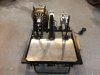
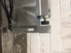
The Brake Pedal (work in progress)

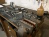
The clutch pedal (Work in progress)
Background:
I used to play Grand Prix Legends back in 2000 with a red Logitec wheel and pedals, dial up internet and a large speaker behind my seat (early tactile!) Then I stopped to concentrate on the build of my race car, which I developed and competed in. It was sold 8 years ago.
Fast forward to 2019 and I happen to see modern day sim racing on you Tube and was very impressed and decided I needed to get back into it.
After lots of research I decided I could build my own pedals quite cheaply. I had previously built a car from scratch, have a work shop with a lathe and TIG plus lots of material left over.
I intend to build the pedals using as much material from stock. So the designs may not be perfect but they make use of the material I have.
Electronics
Using Leo Bodnar components, it appears to be very easy to make transducer and load cells into game controllers. Time will tell if it is really that easy!
Brake
My race car experience taught me that it is easier to modulate pressure than movement, this then dictated that I need a load cell based system rather than a rotary or linear potentiometer. I looked at beam, button and S load cells and looked at prices.
My original plan was to use a beam vertically and mount the pedal directly to it, so in effect a solid pedal. Talking to the electronics guy at work I was advised that the cheap Chinese load cells do not tolerate any side loads, so this idea would not work. He also advised not to overload the load cell.
To get straight motion on the load cell I needed a linear bearing. My race car also had a small about of pedal travel then went solid. So I wanted to replicate this feel.
To understand brake loads so I could specify a load cell I put my bathroom scales in the passenger footwell of my car and pressed hard and noted the loads. I could press 50kg, which equates to around 500N. With leverage and availability I decided on a 100kg (1000N) beam load cell.
Most commercially available pedals feature large amounts of adjustability. I decided I didn’t need this as I was making them for me and not trying to replicate a particular car.
I also considered a hydraulic set up but considered it too complex.
Clutch
I decided I wanted a clutch. I looked at many designs to understand how to get the correct pedal feel of a clutch (increasing pressure then less pressure). All these designs needed springs. I quickly realised that springs are expensive. Plus, I probably would have to play with rates to get the correct feel. That would take time and cost money.
So, I decided to use a real clutch cover. A quick look on eBay indicated new ones can be had cheaply. That would definitely give the correct feel. Originally, I was going to use a master cylinder and concentric release bearing, but then I realised I was again making it over complicated. Why not have a mechanical direct acting set up? It is only a matter of getting leverages correct. Hydraulics give mechanical advantage just as levers do.
I kept an eye on eBay looking for a new small diameter cover, plate and release bearing. Eventually I bought a new small Renault kit for £14 delivered!
After discovering linear bearings I decided linear bearings would be ideal to actuate the clutch.
A rotary pot will be used.
Accelerator
Originally, I was going to use a rotary pot but was concerned about only being able to use a maximum of 120 degree of rotation. I have read articles stating it doesn’t matter that you are not using the whole rotation but I thought if I could it will not harm. I looked at many ways of converting linear motion to rotary such as rack and pinion, cable around a pulley and increasing rotary such as gearboxes but decided that a linear potentiometer would be best. The only downside of linear pots is cost, but I found a couple of options at reasonable cost.
I also looked at hall sensors and discussed them with the electronics guy at work but decided they were not the best solution.
Having discovered linear bearings I decided to use them for the accelerator too.
Brake Detail

The brake is a linear bearing block mounted on a block of aluminium. A 16mm dia rod slides through the middle. A 100kg load cell is bolted vertically. The advantage of the block is it is easy to keep everything square and in line, plus is easy to drill and tap into.
There is a rubber buffer acting on the load cell. This screws into the 16mm dia rod. It is set up with a small gap to the load cell. This will give the initial slight pedal movement.
At the pedal end a Lancia Integrale inner valve spring (had it in stock!) ensures the pedal returns and there is some initial pedal pressure.
The pedal pivots on cartridge bearings which are old ones from my mountain bike pivots. To be honest bearings are not really required due to the very small amount of pedal pivot but as I had them it was cheaper than buying plastic bearings or bushes.


Detail of the pedal end of the linear bearing block. The aluminium disc between spring and linear bearing is held onto the linear bearing with Loctite 638 bearing fit.
The spherical rod ends are M6.

Detail of the rubber buffer and aluminium spacer.

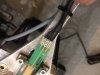
This photo shows how I ensured the linear bearing block was mounted inline. Using the 16mm rod I was able to check everything was in line. The fact that the rod was long amplified any error and made it easier to ensure it was straight.
The 16mm rod is surface hardened. The only way to cut it to length was to grind it using a 1mm thick cutting disc. It was also hard to tap. I had to turn the tap a few degrees and then back it off. Time consuming but I didnt want a tap breaking off in the rod.
Work to do on the brake
Brackets to hold the block onto the box section
Brackets to hold the spherical bearing to the pedal
Spacers either side of the spherical bearing
Weld everything up - My gas has run out and now lock down is easing I should be able to get some more.
Mounts to my rig (which I will build)
Tactile
Tactile
I intend to add some tactile to the set up. First thoughts is an exciter to the pedal stem. I can easily isolate the above set up and isolate my heel pad. In fact I can easily isolate every pedal and every heel plate separately from each other and the rig. My plan is to build this in so I can add tactile as I learn about it / choose what to do.
I am currently researching isolators so I know the best to use.
Next time the clutch.
First a few photos of the work so far before I get into the detail.
The Brake Pedal (work in progress)
The clutch pedal (Work in progress)
Background:
I used to play Grand Prix Legends back in 2000 with a red Logitec wheel and pedals, dial up internet and a large speaker behind my seat (early tactile!) Then I stopped to concentrate on the build of my race car, which I developed and competed in. It was sold 8 years ago.
Fast forward to 2019 and I happen to see modern day sim racing on you Tube and was very impressed and decided I needed to get back into it.
After lots of research I decided I could build my own pedals quite cheaply. I had previously built a car from scratch, have a work shop with a lathe and TIG plus lots of material left over.
I intend to build the pedals using as much material from stock. So the designs may not be perfect but they make use of the material I have.
Electronics
Using Leo Bodnar components, it appears to be very easy to make transducer and load cells into game controllers. Time will tell if it is really that easy!
Brake
My race car experience taught me that it is easier to modulate pressure than movement, this then dictated that I need a load cell based system rather than a rotary or linear potentiometer. I looked at beam, button and S load cells and looked at prices.
My original plan was to use a beam vertically and mount the pedal directly to it, so in effect a solid pedal. Talking to the electronics guy at work I was advised that the cheap Chinese load cells do not tolerate any side loads, so this idea would not work. He also advised not to overload the load cell.
To get straight motion on the load cell I needed a linear bearing. My race car also had a small about of pedal travel then went solid. So I wanted to replicate this feel.
To understand brake loads so I could specify a load cell I put my bathroom scales in the passenger footwell of my car and pressed hard and noted the loads. I could press 50kg, which equates to around 500N. With leverage and availability I decided on a 100kg (1000N) beam load cell.
Most commercially available pedals feature large amounts of adjustability. I decided I didn’t need this as I was making them for me and not trying to replicate a particular car.
I also considered a hydraulic set up but considered it too complex.
Clutch
I decided I wanted a clutch. I looked at many designs to understand how to get the correct pedal feel of a clutch (increasing pressure then less pressure). All these designs needed springs. I quickly realised that springs are expensive. Plus, I probably would have to play with rates to get the correct feel. That would take time and cost money.
So, I decided to use a real clutch cover. A quick look on eBay indicated new ones can be had cheaply. That would definitely give the correct feel. Originally, I was going to use a master cylinder and concentric release bearing, but then I realised I was again making it over complicated. Why not have a mechanical direct acting set up? It is only a matter of getting leverages correct. Hydraulics give mechanical advantage just as levers do.
I kept an eye on eBay looking for a new small diameter cover, plate and release bearing. Eventually I bought a new small Renault kit for £14 delivered!
After discovering linear bearings I decided linear bearings would be ideal to actuate the clutch.
A rotary pot will be used.
Accelerator
Originally, I was going to use a rotary pot but was concerned about only being able to use a maximum of 120 degree of rotation. I have read articles stating it doesn’t matter that you are not using the whole rotation but I thought if I could it will not harm. I looked at many ways of converting linear motion to rotary such as rack and pinion, cable around a pulley and increasing rotary such as gearboxes but decided that a linear potentiometer would be best. The only downside of linear pots is cost, but I found a couple of options at reasonable cost.
I also looked at hall sensors and discussed them with the electronics guy at work but decided they were not the best solution.
Having discovered linear bearings I decided to use them for the accelerator too.
Brake Detail
The brake is a linear bearing block mounted on a block of aluminium. A 16mm dia rod slides through the middle. A 100kg load cell is bolted vertically. The advantage of the block is it is easy to keep everything square and in line, plus is easy to drill and tap into.
There is a rubber buffer acting on the load cell. This screws into the 16mm dia rod. It is set up with a small gap to the load cell. This will give the initial slight pedal movement.
At the pedal end a Lancia Integrale inner valve spring (had it in stock!) ensures the pedal returns and there is some initial pedal pressure.
The pedal pivots on cartridge bearings which are old ones from my mountain bike pivots. To be honest bearings are not really required due to the very small amount of pedal pivot but as I had them it was cheaper than buying plastic bearings or bushes.
Detail of the pedal end of the linear bearing block. The aluminium disc between spring and linear bearing is held onto the linear bearing with Loctite 638 bearing fit.
The spherical rod ends are M6.
Detail of the rubber buffer and aluminium spacer.
This photo shows how I ensured the linear bearing block was mounted inline. Using the 16mm rod I was able to check everything was in line. The fact that the rod was long amplified any error and made it easier to ensure it was straight.
The 16mm rod is surface hardened. The only way to cut it to length was to grind it using a 1mm thick cutting disc. It was also hard to tap. I had to turn the tap a few degrees and then back it off. Time consuming but I didnt want a tap breaking off in the rod.
Work to do on the brake
Brackets to hold the block onto the box section
Brackets to hold the spherical bearing to the pedal
Spacers either side of the spherical bearing
Weld everything up - My gas has run out and now lock down is easing I should be able to get some more.
Mounts to my rig (which I will build)
Tactile
Tactile
I intend to add some tactile to the set up. First thoughts is an exciter to the pedal stem. I can easily isolate the above set up and isolate my heel pad. In fact I can easily isolate every pedal and every heel plate separately from each other and the rig. My plan is to build this in so I can add tactile as I learn about it / choose what to do.
I am currently researching isolators so I know the best to use.
Next time the clutch.
Attachments
Last edited: