Building my Own f1 wheel MP4-26 inspired

Hello folks,

Some months ago i started working on an old simracer dream that i have.
I want an f1 cockpit replica, with wheel and pedal set as close as possible as the real thing.
I started with the steering wheel design process since it is the the most sourced (infos) thing of the whole project.
I'm an "IT guy" but my shool background is more about technical drawings, automatism and machining, but this was 20-25 years ago :p.

My wheel project is inspired by the Mclaren MP4-26 steering wheel and based on an SLI-Pro since the SLI-f1 seems to be abandoned or at least delayed to nowhere :p

It will come with :

9 Buttons
2 Toggle Switchs
4 Shifting pads
2 Analog pads (for clutch or anything else ^^)
6 Rotary switches (its missing on from the real thing but sli-pro only manages 6 if i'm correct).

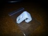
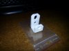
The design is almost complete, most of the parts have been modelled including switchs, rotary swith or encoders, this will prevent bad surprises when I will send the cad files for machining and assembling the whole thing after that :p.

A lot of polishing to do, i hope to be able to have my first wheel around July or August 2013 as well as the pedal set which the design as not been started yet.

View attachment 36939
9bis.jpg
10bis.jpg
11bis.jpg
 
Have you read the topic on f1 technical? Apparently it's even in the technical rulebook that both paddles need to have the same 'calibration' so to speak. Whether that is true or not remains to be seen...

Richard Leeds said:
I picked up on your comment about the second one being being "set". The driver has to manually hold it at the biting point, they are not allowed to have any notch or indicator for that. The key point is that both paddles have to be identical.

edit:
Apparently, it is i the technical regulations:
9.2 Clutch control :
The following applies only to the main drivetrain clutch or clutches, any clutch used exclusively as part of a KERS is exempt.

9.2.1 If multiple clutch operating devices are used, they must all have the same mechanical travel characteristics and be mapped identically.

9.2.2 Designs which allow specific points along the travel range of the clutch operating device to be identified by the driver or assist him to hold a position are not permitted.

9.2.3 The minimum and maximum travel positions of the clutch operating device must correspond to the clutch fully engaged normal rest position and fully disengaged (incapable of transmitting any useable torque) positions respectively.

9.2.4 Designs or systems which in addition to typical inherent hydraulic and mechanical properties are designed to, or have the effect of, adjusting or otherwise influencing the amount, or rate, of engagement being demanded by the FIA ECU, are not permitted.
 
Upvote 0
ASAIK both paddles do the same. Both as used on launch as one is held at the biting point and one is fully depressed. Whichever has the most travel on it is the active one.

So for the start, one is held at the BP (point is usually set via wheel control on the formation lap) and one is fully depressed. Rev's are raised then the fully depressed clutch is released, kicking in the 2nd paddle which is held on the BP. From there it is slowly released the same way you'd pull away with a foot clutch. As above technical regs seem to say you can't have the 2 paddles mapped differently, holding it at the BP is just part of a drivers skill.


From around 2:30 DC is explaining how he finds the BP and the start procedure in the RedBull simulator.
 
Upvote 0
Hi guys, thanks for your inputs

@Hampus, many works to do to polish it, let me finish the first one, who knows if there will be other ones, it will depend of the price requested to build the whole thing :p
But yes i have in mind the possibility to sell extra ones if i can make them affordable.

William, i choosed to use two analog pads not only for clutching, it could be used to brake or accelerate as well.
or being able to clutch with right or left hand =)
 
Upvote 0
Small update here on how the things are going on.

First and important point ,I know now that my project will become true ! its in my money range to do a first prototype that will be perfectly usable for myself.
I've contacted some 3d printing website and requested some quotation and the price even if they are expensive stay in the bugdet.
It will take some months to buy and built all the parts but, i think that my august deadline could be respected.

Second point, i'm going to add more details to the wheel to make it more accurate to the real thing especially backside and grips ^^ since some of the "machining" limitation i had are now gone with 3d printing =).
My issue was the way of doing the backside cover of the wheel, i had to build a mold for it, but now its useless =)

I just had my hands on my first knitter pushbutton and the quality (and weight....) is amazing, nice feeling.
For the shift pads i'm going to use some footswichs from guitars pedals, more stronger and pretty unbreakable and cheaper as well...

William,

Thanks for the infos regarding the quick release, but i'm not sure to understand what you meant.
I'm going to produce everything except quick release and electronic componants of course.
That means, plate, grips, backside cover, quick release support, button plate, sli box, shift pads ect ect...
 
Upvote 0
I was away for the weekend so couldn't reply earlier. You don't have to know any distances for the bolts, the diameter of their pattern is enough :) This is a standard for these types of quick releases, 50mm (for regular ones it's usually 70mm). All you have to do is arrange for three points on that circle every 120 degrees and you are set :)
vfcoee.jpg
 
Upvote 0
Hi William, thanks for the details, this is a good help to check my design :p
Main plate is giving me hard time with quotations i get from my french local online machining sites...huge prices.
I'm looking for uk, spain, italia , belgium or deutsh machining site if someone know one.
 
Upvote 0
Hi Folks,

I should receive my first prototype part tomorrow, its just one of the analog pad support.
This is just a test to have a real part in my hands to see solidity, flex and other things.

Have to say i'm pretty excited since its the first step to the final stair :p

I'll give you an update :p
 
Upvote 0
Here are the pics of my first designed part received yesterday.

Solidity is more than expected as well as flexibility,
Good point with havinbg the real part in hands is that you see immediatly what can be changed and improved.
 

Attachments

  • Analog support.jpg
    Analog support.jpg
    167.2 KB · Views: 448
  • Analog support 2.jpg
    Analog support 2.jpg
    156.8 KB · Views: 456
Upvote 0
I used the poorest material the company is offering and i pretty satisfied.
First thing i did after checking flexibilty and aspect, was throwing the thing on the floor to test solidity (yes i know....its brutal :p) and it did not fail.

The main plate of the wheel will be made of 5mm aluminium, only the back cover and some internal parts will be printed as well as the rotary knobs wich i have not been able to find thru internet.
 
Upvote 0

Latest News

Are you buying car setups?

  • Yes

  • No


Results are only viewable after voting.
Back
Top