G27/G29 Hall Sensor Mod

GeekyDeaks

Staff
Premium
Thought it might be an idea to share some ideas @Neilski and I have been bouncing around about replacing the stock pots in the G27 and G29 with Hall Sensors (probably also work on a G25). We found a few discontinued options (e.g. https://www.simulaje.com/productos/accesorios/sensor-hall.html) and a current one that seemed ok but required a USB adapter (https://tomyracing.com/index.php?language=en&module=products&content=pedhallv130), which made us suspect its range might not be great and/or it didn't invert the signal. (EDIT: I didn't read the description properly! the mod can be used without a USB adapter)

So, in the interests of science we decided to get some bits and have a play. We went for the A1324/5/6 (https://docs.rs-online.com/958c/0900766b813d193a.pdf) as it appeared to have decent range of close to 0-Vcc (many are just +/-1v) and @Neilski worked out a simple arrangement that theoretically would produce a near linear change based on angle over the 70 deg the G2X rotates the pot:

1600181340738.png


This was then a great excuse to get a 3D printer, so I ordered an Ender 3 Pro (https://www.creality3dofficial.com/products/creality-ender-3-pro-3d-printer) and knocked up a simple model to hold the magnet and sensor whilst still utilising the existing pot for simplicity. The result was the following:

g2x_mag1.jpg


IMG_20200913_155039.jpg

Assembled and connected up to an Arduino to measure against the pot
IMG_20200913_164101_2.jpg


It's got an interference fit that seems fine and allows adjustment of the sensor angle to get the range as centred on Vcc/2 as possible. We played with some different magnet sizes, but found the 8mm with the most sensitive device (A1324) gave a range just over that of the stock pot. BLUE line is the pot, RED is the hall sensor

hall-v-pot-8mm.png

We are still playing but this is looking really promising as a simple swap for the standard pots in the G27 and everything but brake in a G29, although a less sensitive device like the A1326 could probably get the range down to that expected (more testing required!)

EDIT: forgot the link to the 8mm model - https://a360.co/3mvHXkX
 
Last edited:
Hello good! I have followed some things in this post regarding how the sensor works and I have not been able to hit the nail on the head, a friend has a sensor mod that when measuring the voltage on the accelerator pedal, it is obtained.

on break :
red wire: 3.2v
Black wire: 0v
Remaining Wire: 3.14v

when using it:
red wire: 3.2v
Black wire: 0v
Remaining Wire: 0.2v


we try to replicate it, however we have tested the A1302, A1324 and an SS49e sensors and in all three cases we get

on break :
red wire: 3.2v
Black wire: 0v
Remaining Wire: 2.5v

when using it:
red wire: 3.2v
Black wire: 0v
Remaining Wire: 0.82v

What is this voltage difference due to? Could it be the type of sensor or something we are not overlooking

The only thing we have been able to identify from the sensor is that it has "2131 195L" inscribed on it.

367544068_2009242186091938_415720204663858902_n.jpg


greetings!
 
Last edited:
Upvote 0
What is this voltage difference due to? Could it be the type of sensor or something we are not overlooking
If I had to guess, it would be how the sensor is moving through the magnetic field. Can you take a picture of the entire assembly so we can see the arrangement? For reference, it's far better to measure rotation of a magnet with a hall sensor than linear displacement, assuming it can be done that way easily enough of course.
 
Upvote 0
the sensor is oriented in a similar way to the following scheme, today reviewing the matter with my friend who owns the mod, we detected that the sensors that it has "work" as they should, the voltages reach both the minimum and the maximum without leaving zones dead

something different from when we did the voltage measurement with a sensor that by the way I bought from aliexpress... I am seriously considering the option of seriously acquiring one allegro somehow :roflmao:

Sin título.png
 
Upvote 0
the sensor is oriented in a similar way to the following scheme, today reviewing the matter with my friend who owns the mod, we detected that the sensors that it has "work" as they should, the voltages reach both the minimum and the maximum without leaving zones dead

something different from when we did the voltage measurement with a sensor that by the way I bought from aliexpress... I am seriously considering the option of seriously acquiring one allegro somehow :roflmao:

View attachment 689918

I have some Alegros laying around and could part with 1, which type are you looking for?
 
Upvote 0
the sensor is oriented in a similar way to the following scheme, today reviewing the matter with my friend who owns the mod, we detected that the sensors that it has "work" as they should, the voltages reach both the minimum and the maximum without leaving zones dead
ah, gotcha.... ok then, that looks like the hall sensor from ali is either less sensitive or cannot go rail-to-rail. I'm not able to find any details on the original part, but you said you tested with an A1324, correct? That is quite a sensitive device at around 5mV/G (the A1302 is only 1.2mV/G) and does go rail-to-rail. I'll try and see if I can find another sensor that is even more sensitive
 
Upvote 0
Well, today I managed to check many things and finally I am seriously considering that the problem is being generated by the "replica" sensors, I will try to acquire some original Allegro ones and hoping that the measurements are as expected, I'll let you know how it turns out for me


thank you for the help! :D !
 
Upvote 0
Hello good! I have followed some things in this post regarding how the sensor works and I have not been able to hit the nail on the head, a friend has a sensor mod that when measuring the voltage on the accelerator pedal, it is obtained.

on break :
red wire: 3.2v
Black wire: 0v
Remaining Wire: 3.14v

when using it:
red wire: 3.2v
Black wire: 0v
Remaining Wire: 0.2v


we try to replicate it, however we have tested the A1302, A1324 and an SS49e sensors and in all three cases we get

on break :
red wire: 3.2v
Black wire: 0v
Remaining Wire: 2.5v

when using it:
red wire: 3.2v
Black wire: 0v
Remaining Wire: 0.82v

What is this voltage difference due to? Could it be the type of sensor or something we are not overlooking

The only thing we have been able to identify from the sensor is that it has "2131 195L" inscribed on it.

View attachment 689736

greetings!
Hello, 49e is not good sensor for this, because like you checked 0.8 it's the minimum (You can check it in the Datasheet, it's normal behavior) and the max at 5V it's 4.2V my clutch has this sensor (it's good because i use a big cuts in the first steps and last), but i bought a new one (95A from ali - SS495A) for the accelerator, now i got the 100% of pedal travel. I bought this one because has 0 to 5V or 0 to 3.3V linear. I only use one magnet 15mm long, cylindrical, because has the poles in the tops. I put 2 pictures of my setup. It's only one magnet and one sensor, cyanoacrylate and a piece of wood... haha...

actually, has different magnet, like i said 15mm long x 5mm cylindrical. But in the same place. Only the piece of wood it's different, i don't have photo of the last mod. And i don't want to open the pedals. But it's very intuitive how i did this. Where you see two magnets (7mm long and 8mm diameter total 14mm long with both) it's the clutch, and this one has no changes. The other with big magnet was the accelerator pedal. Now with the 95A and 15mm magnet.

You also can use magnet with 20mm long, maybe de calibration it's more easy. But you got a lot of positions possible. you need to move the piece of wood with the sensor attached to it till you get the 0% to 100% of travel, using the DiView app. The best way to do it it's put a pencil to mark the correct position of the magnet. where the travel of the magnet it's linear. Just press the pedal 0% to 100% to mark the black piece.

Careful with rectangular magnets, because the poles of the magnet are in the faces, and not in the tops. then you can't use this linear, and you need two of them and different setup. More complex.

i did a 50Kg Cell brake without any extra Oamp only one pressure sensor and one resistor, with a new 40kg spring, and work pretty good on PC, can't work in console.

1698038064425.jpeg

1698038064437.jpeg
 
Last edited:
Upvote 0
ah, gotcha.... ok then, that looks like the hall sensor from ali is either less sensitive or cannot go rail-to-rail. I'm not able to find any details on the original part, but you said you tested with an A1324, correct? That is quite a sensitive device at around 5mV/G (the A1302 is only 1.2mV/G) and does go rail-to-rail. I'll try and see if I can find another sensor that is even more sensitive
He returned after a while hahaha, it was difficult for me to find the sensors.... I can finally say that they work, I have tested the A1302 sensor and there is only a 5% loss that can be solved by recalibrating or changing the saturation within a game, I'll try to get A1324 sensors to see how it goes.

Thank you very much for all the help!
 
Upvote 0
He returned after a while hahaha, it was difficult for me to find the sensors.... I can finally say that they work, I have tested the A1302 sensor and there is only a 5% loss that can be solved by recalibrating or changing the saturation within a game, I'll try to get A1324 sensors to see how it goes.

Thank you very much for all the help!
What do you mean with 5% lost? there is something wrong. I checked the datasheet, and it's because the hall sensor has 0.2 to (Vs -0.35) V. Vs (voltaje source) it's 3.25V with g29, Then should be 0.2V to 2.9V. Try the hall sensor which i recommended in my previous post it's very cheap, and with my setup works fine from 0V to 3.25V. And in the DiView goes from 0% to 100% 0 to 255 steps (8bits). I will take a picture tomorrow for show you.

Other possibility can be the magnets the distance to the hall sensor it's wrong.

Let me ask you, the 5% is it in the first travel of the pedal or in the final?
You can change where is it changing the magnets, i mean the poles of the magnet, you are using 2 then just invert them. And after this you need to invert the axis in the games.

Check this, this is under 5Vcc Vs

1698718915678.png
 
Last edited:
Upvote 0
Hello

I understand that this thread is old, but I need some guidance as I have followed everything, and it's not giving me any results of any kind. I know I must be missing something, but I don't know what the problem is.

I have my G29 pedals connected to an Arduino Leonardo so that I don't depend on the entire base. I bought the A1324LUA-T hall sensor on AliExpress, and unless I have it wrong for polarity, it does nothing in the Windows calibration options. I've also tried another hall sensor, the SS495A1, as I've already converted T16000M joysticks to hall sensor, but I don't see it doing anything either.

Now that you have some context, I have a few questions. Should I disconnect the other potentiometers as well, or does that not matter? I ask because I'm trying to test if the hall sensor reacts when I bring the magnets close, and I haven't disconnected them.

Well, for now, that's it, and I'm sorry if I've revived the thread, but I don't know who else to turn to, and for now, I don't have a functioning pedal set.

Thank you very much for your guidance.
 
Upvote 0
I've also tried another hall sensor, the SS495A1, as I've already converted T16000M joysticks to hall sensor, but I don't see it doing anything either.
Assuming that you have already verified the SS495A1 is working ok, could you share a bit more detail of the setup you have for the pedals, e.g. a pic or two that we can use to determine the circuit?
 
Upvote 0
It's really tricky to tell how you wired up the sensor, but it looks like you have the signal wired to the middle pin instead of GND. Can you show us a bit more detail on how you have it connected?
 
Upvote 0
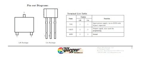
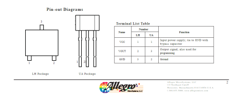
But signal is not the pin 2? The middle one? I followed the datasheet and the pin out say that:
Captura de pantalla 2024-02-04 220351.png
So now I'm a lil bit confused. Anyway tomorrow I can swicht the wires and try again.
Thanks for your help! :)
 

Attachments

  • Captura de pantalla 2024-02-04 220351.png
    Captura de pantalla 2024-02-04 220351.png
    20.4 KB · Views: 30
Upvote 0
The resolution of the images for the pinouts is too low to properly tell, but it looks suspiciously like the UA packaged sensor has Vout on pin 3.... Can you share the datasheet so we can take a look at it?

EDIT: it's ok, I'm just dumb :). I looked directly at the attachment and I can see that the UA package pinouts have Vout on pin 3. I suspect you just have GND and Vout swapped
 
Last edited:
Upvote 0
Hi!
First of all, thanks for your reply, yeah, you were right, the pin was swapped and now It's working but now I have another problem, so I made another video beacuse is very odd


Thanks for your help!
 
Upvote 0
Nope, still nothing but I think maybe it's the sensor. If you can see I need to put the magnet very close to the sensor and when is inside of the piece, there is not any response.
So I was thinking about a piece wich is similar to this:


So I was wondering If this piece is exist on webs like thingyverse or I need to made myself, wich that is a big problem beacuse I don't have any experience in desing piece.
Anyways, thanks for your reply's :)
 
Upvote 0

Latest News

Are you buying car setups?

  • Yes

  • No


Results are only viewable after voting.
Back
Top