DIY Hydraulic Pedals

Hey all ,

I started sim racing around 16 months ago , it was after 6 odd months that i started getting some trouble from my CSP's , that i decided to explore the prospect of building something of my own . So with the help of a friend of mine (he has electronics knowledge, i have none :D) i set about what you see below ...

So here we go ....

I have to say a big thankyou before anything else to Phil Berry for all his help and words of encouragement !

Like any project its the slow and painful process of acquiring bit on a parts by parts basis .....

So this is what i have managed to receive thus far :

DSC02051_zpsa5eed04c.jpg


Magnets for the Hall Sensors

DSC02054_zps1b8ad685.jpg


These being the Hall Sensors ( tiny little things)

DSC02052_zpsb38b21fa.jpg


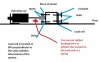
Pressure transducer for the clutch

DSC02053_zpsc19d4359.jpg


Measpec transducer for the brake
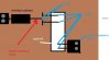
DSC02055_zps3bb38f90.jpg


Pull slaves

DSC02056_zps3dca8c9e.jpg


I have 2 types of valve springs that i will be using on the pull slave , depending on how hard or soft you want the effect to be

340-12410-lg_zps4113b68a.jpg


The pedal assembly (pièce de résistance in my opinion)

260-1304-lg_zpsf1e43fca.jpg


Master for the clutch pedal

260-3374-lg_zpsa1c735e3.jpg


Masters for the brakes

hpim1547_zpsa17c0074.jpg


Load cell amp (many thanks to derek speare)

Thats all i have for now , so as i accumulate more gear and finally begin the construction i will post more pics ...
 
http://www.varjanta.com/forum/hydraulic-brake-pedal-handmade-t1808.html take a look here it is a very good project it uses a "dry" load cell in the middle of the pads and springs. This kind of load cell could be good too for the purpose you can install it in the middle or end of the rubber stack/spring in the slave cylinder, i think i looked for price info but very difficult to find and ther ones that accepts big loads are expensive from what i remember.

i forgot to mention the loadcell type is a donut load cell as this http://www.directindustry.com/prod/...type-compression-load-cells-14287-573518.html
 
Upvote 0
Wow some hi-tech stuff for sure. I am pretty happy with my CSP v1's and v2's but a WMD member is doing a build with the Tilton pedals and seeing that got my interest up. Just the technology and high quality behind what you are doing is very fascinating. Great work you guys.
 
Upvote 0
Hi Psydfx. May I ask why useing two different types of pressure transducers? Like the one from ebay and the other from Measpec?

Hi Tanimura ,

The eBay sensor is just a cheaper and less accurate PT . Hence why its used on the clutch pedal . The Measpec gives a very fine and stable signal output , something which is necessary for the brake pedal .

Cheers
 
Upvote 0
Hello Psydfx!

Very nice DIY pedals You'v made! I'm trying to make my own hydraulic brake at the moment. Can You explain me how is coresponding value of psi of your pressure transducer with pedal calibration through Dereks controller? Is it very important to choose psi right, otherwise You cannot achive 100% braking in sim?

Great stuff once again!

EDIT: Maybe the brake is not a good example in Your case, because You cant amp it. Better to konw for me is how You make it with a clutch. My first project will be not so exspensive so I'll try the cheaper sensor (3 pin) for my brake.
 
Last edited:
Upvote 0
Hello Psydfx!

Very nice DIY pedals You'v made! I'm trying to make my own hydraulic brake at the moment. Can You explain me how is coresponding value of psi of your pressure transducer with pedal calibration through Dereks controller? Is it very important to choose psi right, otherwise You cannot achive 100% braking in sim?

Great stuff once again!

EDIT: Maybe the brake is not a good example in Your case, because You cant amp it. Better to konw for me is how You make it with a clutch. My first project will be not so exspensive so I'll try the cheaper sensor (3 pin) for my brake.

I´ve recommend you to use the ratiometric milivolt cause you can adjust it with the pot if you use a dsd board the max point, for the milivolt transducer is recommended a 1000 psi one i guess this is more than necesary, i have on the clutch a 500 psi one, maybe this is a little over but i have yo try it, im making hydraulic pedals too only the electronics is left, waiting for a suitable box to hide the circuit
 
Upvote 0
Hello Psydfx!

Very nice DIY pedals You'v made! I'm trying to make my own hydraulic brake at the moment. Can You explain me how is coresponding value of psi of your pressure transducer with pedal calibration through Dereks controller? Is it very important to choose psi right, otherwise You cannot achive 100% braking in sim?

Great stuff once again!

EDIT: Maybe the brake is not a good example in Your case, because You cant amp it. Better to konw for me is how You make it with a clutch. My first project will be not so exspensive so I'll try the cheaper sensor (3 pin) for my brake.
Gorzasty ,

Firstly thankyou !!

I used the DSD board with load cell amplifier so i can amp up the signal , i used a higher quality PT for fidelity , it has no noise as opposed to the cheaper ebay/sam sensor . And yes i can and do achieve 100% braking in sim , hope this clears the air a little for you
 
Upvote 0
I´ve recommend you to use the ratiometric milivolt cause you can adjust it with the pot if you use a dsd board the max point, for the milivolt transducer is recommended a 1000 psi one i guess this is more than necesary, i have on the clutch a 500 psi one, maybe this is a little over but i have yo try it, im making hydraulic pedals too only the electronics is left, waiting for a suitable box to hide the circuit

Thx very much for advice 3ller. The problem is I've got no so high budget - ebay sesnsor is 36$ plus 8$ shipping and MeaSpec with shipping would be around 170$ so the difference is huge! I know the seckond one is much better, but I'm not sure do I feel this while driving.

I was thinking about third option - to simulate break pedal with master and slave cylinder plus LC, but without pressure sensor. LC is much chipper than the better one sensor and has similar parameteres. So there wolud be master cylinder with fluid to slave cylinder (not pull but push one) and lever of slave would push through a spring on LC. What do U think?

BTW I'm looking forward to see Your project
 
Last edited:
Upvote 0
Gorzasty ,

Firstly thankyou !!

I used the DSD board with load cell amplifier so i can amp up the signal , i used a higher quality PT for fidelity , it has no noise as opposed to the cheaper ebay/sam sensor . And yes i can and do achieve 100% braking in sim , hope this clears the air a little for you

Thx Psydfx for Your answear. I know waht U are talkin' about but that is why I edited my earlier post. I'm wonder how do U calibrate the clutch througt the chipper sesnor and how it's coresponding with stiffness of the pedal. Your brake is ok for me, but You've chosen the more expensive solution.
 
Upvote 0
I was thinking about third option - to simulate break pedal with master and slave cylinder plus LC, but without pressure sensor. LC is much chipper than the better one sensor and has similar parameteres. So there wolud be master cylinder with fluid to slave cylinder (not pull but push one) and lever of slave would push through a spring on LC. What do U think?
I thought on something similar to your idea of a load cell and this type "donut load cell" ,google it (futek and honeywell builds them sure other brands too), would suit very well for the purpose you can put it between the rubber stack on the pull slave cylinder, the problem i didnt know where to find a cheap one for the project and gone the easy and proven way, on this page http://www.varjanta.com/forum/hydraulic-brake-pedal-handmade-t1808.htm there is another approach it uses a real caliper and a load cell between a compression one the difficult thing is search something suitable at a good price, btw the pressure transducer price have come up lately it was over 100 € shipping included for me in the time, maybe 125 130 now im talking on memory here
 
Upvote 0
Yes, quite good example 3eller, but in my opinion 100kg could be to much. I'm guessing but in Derek's 12bit controller You can attenuate the output signal with a pot, not gain it. This is common rule in electronics. Fanatec V2 pedal uses about 60kg but U press directly on the sensor. We want to use cylinders, co there will be different (maybe smaller) force acting on LC. In my country you can buy rectangular load cell for 34$ (60kg). It works like this:
.
I can see some mechanics problems with pushed slave cylinder, but it's far more chipper so it's worth of trying.
Thx also for the link with this project that guy uses foliage load cell. Very nice idea, but I dont know where to buy one with electronics (I thinh he uses the one from AP Electrix) - I mean with this small board attached to it, and there is another problem with it - it has only 3 outputs so U can't amp it as U wish.
 
Upvote 0
yes is an aplectrix mod, what do you think about the donut load cell?? i think is a perfect solution but i think the problem is to find something cheap. for the mechanics you could use a L bracket on the floor bolted to the cell maybe?? and on the other side the slave pushing (push cyl)? or if pulling you can put a square piece of metal with a hole in the center passing through the slave cylinder rod between two nuts one against the other and then bolted to the load cell, you could put some rubber bushings too between that metal piece and the end of rod travel to soften the force applied to the cell. Sorry for my english hope you understand
 
Upvote 0
No problem, my English is not perfect too, and Yours is very understandable ;) I'm trying to imagine Your vision and I think is quite ok. I would not rather bolt in the cell. You can damged it easily. Firtsly I'll try to do something with a chip load cell (the rectangular one) and the spring. I don't know how to do it yet ;) but have to figure something out. If I build something I'll show you here.

Donut LC - I can see they are designed generally for higher kg. Other parameters are similar. From the construction point they may be interesting but, as You said, they are exspensive.

For now I have to buy slave cylinder, some pipes to connect it withe master, wait for Derek controller and do some reserach with the pedals. Next I decide what should I buy - LC, pressure sensor and if the second option - the more or less precise. Than l'll show You effect of my work here ;)
 
Last edited:
Upvote 0
i think you didnt fully undertand mi idea is with the typical elane rectanguar load cell, i did a little draw for you, i think it could work. the slave is hold by another L bracket and bolts dont show in the draw. There is 4 bolts connected to load cell each side only show 2 each side cause of perspective, The piece of metal could be rectangular one with a hole in the center or a very big whaser
 

Attachments

  • Hyd pedals.jpg
    Hyd pedals.jpg
    44.2 KB · Views: 1,158
  • Hyd 2 zenital.jpg
    Hyd 2 zenital.jpg
    32.5 KB · Views: 770
Last edited:
Upvote 0
Now I fully understand ;) But i've heard there are different LC for pushing and pulling. For pulling there are "S" shaped I think. Rectangular LC are for pushing ones so I dont know does it will work...another thing that your project use pull cylinders insted of push that are chipper. For me it's important to keep good funcionality/price ratio ;) Have to look in Internet for some projects with LC like this one:

Maybe there are more ideas with pushing on LC ;)
 
Upvote 0

Latest News

What would make you race in our Club events

  • Special events

    Votes: 25 22.5%
  • More leagues

    Votes: 23 20.7%
  • Prizes

    Votes: 21 18.9%
  • Trophies

    Votes: 10 9.0%
  • Forum trophies

    Votes: 6 5.4%
  • Livestreams

    Votes: 20 18.0%
  • Easier access

    Votes: 65 58.6%
  • Other? post your reason

    Votes: 14 12.6%
Back
Top