I'm
selling my GS-5, after building a custom seat. The GS-5 is pretty great, so naturally the question came up... what's so great about the new seat that you'd sell your GS-5?
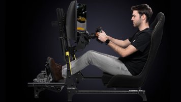
The new seat is basically a 6-direction belt tensioner. You get front, back, left, right, up, and down. Sustained pull of about 40 lbs (I think - I forget what I settled on for mechanical advantage and motor torque soft limit), while at the same time being responsive enough to reproduce small vibrations up to around 200 Hz.
Putting it on takes slightly more time than a 5-point harness. Four belts to snap together, one pair to slip over your shoulders, and one you just sit back against.
View attachment 514902
(More pictures attached)
How does it work?
Six
servo motors running in torque mode, mounted to a custom housing that spools up the tension rope - similar to how a direct-drive belt tensioner works. The spool diameter gives control over speed vs pull force, and the servos are also software-limited to a maximum torque to prevent overheating them (and secondarily for safety).
A microcontroller running custom firmware commands the torque setting for the servos. Knowing the spool and rope diameters, an estimate of friction, and the servo max torque settings, you can easily command the tensioners to produce a specific force amount for the user.
I also have custom telemetry processing software running on my PC and talking to the games to convert telemetry into force settings. I've found that just using the car's local coordinate frame acceleration produces great results, but I can also mix in other effects.
The tension ropes run through custom idler pulleys, which lets them go around corners without rubbing, keeps friction low (important later), and keeps the ropes in a constrained location (so they don't fall off when slack). These ropes then connect to 2" webbing (seat belt material) and to a pair of 1" shoulder loops (downward pull direction).
Low friction on the rope path is important. You need to keep the ropes always tensioned a small amount - any slack in them will reduce response time, the ability to reproduce small vibrations, and introduce a "dead zone" when transitioning e.g. from left to right belt tensioned. The more friction on the rope path, the more baseline torque you need to apply, and the less dynamic range you have to reproduce effects. Also, the more friction (and the more baseline torque), the less inclined the belts are to "relax" when the opposite belt is engaged - leading to a feeling that the belts just keep getting tighter and tighter, but never releasing.
How does it feel?
In a turn, the left/right belts can pin you to the left/right of your seat, while still also feeling the small twitches of traction, steering adjustments, throttle adjustments, and road surface. Note that the belts simulate the pressure on your body of the car's seat belt or seat, just like a regular belt tensioner, so the direction of tension is opposite that of acceleration.
Accelerating and braking, the front/back belts really show off the high-frequency ability of the servo + custom firmware/software stack. If you bounce off the redline, you can feel the belts twitching due to the small variations in acceleration. Likewise, you can feel your tires slipping as slight twitches in the belts, whether braking (front belt) or accelerating (back belt). You get this at the same time as the larger acceleration / deceleration pin-you-to-your-seat effect.
Up/down belts essentially provide road bump detail and a heave effect on hills.
Kerbs / rumble strips can be felt even at high speeds, thanks to the responsiveness of the system. Which belt you primarily feel them on depends on whether you're cornering or driving straight at the time you hit them.
It's also basically silent. The servos are high-quality and don't produce any sort of high-pitch whine, and there aren't any mechanical parts to make noise.
What could be better?
I'd say the quality of the effect in the left/right directions is "excellent", in the front/back directions is "good", and in the up/down directions is "fair/OK". Mostly each direction is able to reproduce the same effects, so it comes down more to how effectively I was able to place the belts, which is more difficult in the up/down directions.
The belt which pulls you back into the seat needs a slightly different rope path. Right now, the belt loops around your chest, attaches to a Y-shaped set of ropes, and runs through the center of the seat back. This pinches your ribs at high force levels, so I'd like to move the "Y" connection to the rear side of the seat back, and let the rope pass through a pair of holes in the seat.
The downward-pulling shoulder loops work OK, but ideally you'd have that force spread over part of your torso, too. Maybe integrating the belts into a vest would help with this, in addition to making it easier to put the whole thing on.
The upward-pulling belt still needs some work - I'm not satisfied with it - it tends to slip up your back a bit at an angle, instead of providing a true upward pull at your butt/thighs. Again, this has me thinking I need to design a vest system to integrate the belts.
The rope spools need a stronger connection to the motor shaft. They can slip at higher torques. I've partially solved this by drilling through them (and the motor shaft) and inserting spring pins, but I'll integrate something into the design next time. This is partly due to the spools being plastic, too, so I couldn't adhere them as well as a normal shaft-pulley setup.
I'd like to redesign the motor mount and spool enclosure, to make them easier to service. You have to take the entire thing apart to replace the ropes or move it to a different location.
I'd like to swap the
low-stretch rope I'm using for Vectran. Supposedly it is stronger, which means I can use slightly narrower rope and smaller pulleys. It's also even lower stretch, which means the rope can transmit more fine vibration details.
Comparison to my GS-5
I only had the base GS-5, not the belt tensioner add-on. I've heard great things about the combination of the two, and I was also fairly pleased with my GS-5 by itself. I did try some non-destructive modifications to my GS-5:
- 5-point harness to hold you against the paddles. I rarely used it, because it took a bit to put on and I'd inevitably forget something that'd require me to take it all off so I could get out of the seat again... But it did work, when I could be bothered to use it. I think the GS-5's belt tensioner system would be a huge improvement over this in all ways...
- Tactile transducers - LFEs on the left and right mounted to "wings", an LFE hanging off the rear bottom, and a Clark hanging off the upper seat back. This is an effective way to get vibration effects, and I was happy with it, but it requires extra tuning, of course. I was able to use existing mounting points on the seat, with some work.
- Removed the seat cover and foam padding, adhered hard, hand-shaped foam blocks to the paddles, and sat directly on those. This greatly improved the "squeezing" effect to the left and right, and I highly recommend it. It's a great way to make the left/right effects as pronounced as the back-only effects, and it improves your ability to feel vibration effects.
- Custom telemetry software... I already have my own software for controlling my motion platform, tactile transducers, etc. which I'm quite proud of, and I was able to connect my software directly to the GS-5 with some magic. For my personal use, I would say this was a big improvement for me, in terms of being able to choose the exact effects I wanted, add in vibration effects, determine how telemetry gets interpreted, etc.
I could've stuck with my GS-5 and added the associated belt tensioner system. This would've given me front, back, left-ish, right-ish, and up. "Down" with a paddle system is handled indirectly by the "up" paddles going as far in the opposite direction as they can. I've heard great things about this combination, and it more or less has the important stuff covered.
Why design my own?
- I like the challenge - my sim racing hobby has turned into more of a hobby interest in electronics, mechanics, robotics, etc. and I'm getting less interested in the driving. The driving is an awesome excuse and a great way to test it all out
")
- I wanted strong left/right forces - the GS-5 kind of gives you left/right indirectly, by squeezing you at a bit of a diagonal direction. It works, but I wanted to try a different approach. My design can really pull and/or squeeze you, quite a bit.
- The GS-5 is way too noisy for my tastes, especially when reproducing higher-frequency effects.
- The GS-5 struggles with high-frequency effects. I'll give it some credit - I was actually quite surprised how fast it could go for small movements - but the stepper motors get very noisy, cap out at around... I forget, maybe 80 Hz... and lose a lot of their torque at high speed (leading to the paddles slipping).
- I'd like more direct control over the amount of force. Paddles and (most) belt tensioners approximate this by setting a target travel position, not by directly controlling the amount of applied force.
In particular with #4, I have a goal of removing the tactile transducers on my cockpit. I know from experience that servos are capable of high-frequency effects (200Hz+, just like a tactile unit),
if they are paired with a suitable microcontroller and software stack to feed them. (I have made this modification to my motion platform and it's impressive what they can do). Having left/right/up/down/front/back tactile directly connected to you, as opposed to getting muddled up in your cockpit's frame, makes for a big improvement in spatial fidelity.
I'm very pleased with the results, though up/down needs a bit of work on the belt arrangement. It pulls and squeezes hard - you can fight back, but it's quite difficult at full strength. Tactile effects are fantastic, and that's with just using the raw acceleration data (no canned effects, though I could add them). The amount of detail coming through the telemetry exceeded my expectations. I think I did well on the "why?" design bullet points above.
Materials
Seat panels are laser-cut aluminum. Frame is Misumi aluminum extrusion. Rope (low-stretch polyester) and servos (Teknic ClearPath) are linked above.
Webbing and webbing hardware are from McMaster-Carr, and I sewed it together with heavy-duty sailmaker's needles, a "palm" to protect my hand, and pliers to pull the needle through when it got stuck. A heat gun is handy to clean up the ends of the webbing and prevent fraying.
Idlers are 3D printed, with a pair of ball bearings and a shoulder bolt as a rotary shaft. I probably could've done these cheaper and stronger with bent sheet metal, but the Nylon is also nice as it's relatively low friction and won't damage the rope.
Rope spools are 3D printed and pressed onto an aluminum shaft with an arbor press (but as mentioned, this turned out to not have enough holding force), and the shaft is then connected to the servo with a flex coupling. The shaft is supported on both ends by ball bearings, otherwise the radial forces would damage the servo.
The servo mount and spool enclosure is 3D printed with heat-set threaded inserts.
The armrest uses a pair of 3D printed brackets.
Those are all SLS 3D printed Nylon, which is an awesome process (very few design restrictions, no supports, fairly accurate)... but it's also a bit pricey for larger parts, the lead times could be better, and it's not as strong as metal (if you let metal parts of the belt assembly crash into the idlers, they can break).
The seat panels also have a couple SLS 3D-printed plain bearing surfaces to let the ropes pass through without fraying - these are from IGUS's print service.
The microcontroller is an STM32 with a 480 MHz ARM Cortex M7. I put it into a custom board that has connectors for 17 servos total and also controls my motion platform, but you could also grab a $20 Nucleo-144 dev board (specifically one with a stm32h743 chip) and hook up the wires the hard way.
Price for the components, as I built it, is probably a bit more than a GS-5 + belt tensioner add-on. So, it's not a bargain DIY. Mostly the servos push up the price quite a bit.