Hello, thanks for the link. I went through your post. It looks like the pinouts you share are the same that we discovered here.
I think the main difference between our projects is:
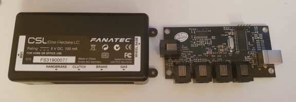
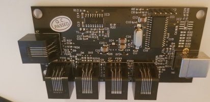
- you have successfully connected 'non-Fanatec' pedals to the CSL control board, essentially through the pin-out mapping. But all of your pedals are directly outputting exactly the signal type expected by the CSL board. (Brake is load cell, throttle/clutch are NOT).
- Your throttle/clutch pedals have hall-effect sensors installed. Which is already what the CSL board is expecting to see, on the throttle and clutch input.
- So in the end, yes, it's a successful proof that non-fanatec pedals can be used with basic wiring checks. As long as the pedal used, is sending the same signal type expected by the control board input.
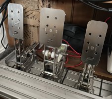
- For my project, the throttle and clutch HE pedals are both load-cells. Which is NOT what the CSPv3 control board (nor the CSL board you use) is expecting for the throttle and clutch inputs. So, that's why we used the load-cell amps on those 2x pedals/inputs (clutch/throttle), and convert the signal. If I understand your project correctly, you didn't do that, or didn't get it to work. Thanks to a lot of help and guidance from some kind people here, we got it working well.
Thanks again and good luck to anyone venturing down a similar path.