Yes, I think that should work OK for the switch detection.
For the LEDs, I'm not seeing anything very clear on the product page, but some of the comments suggest that a resistor isn't needed. However, I would personally play it safe and connect a resistor at first, just in case.
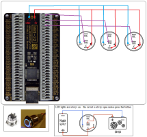
If you allow for a forward voltage of say 1.8 V (should be about right for a red LED), and choose say 5 mA for the current, you'd be trying to drop 3.2 V across the resistor (for a total of 5 V) so you'd choose a resistor in the ballpark of 640 ohms. Then you could measure the voltage across the LED (or perhaps it's an LED+resistor combination of course) and if the voltage is significantly higher than 1.8 V then you've probably already got a resistor in there with the LED (and you'll also probably have a pretty
dim LED
")
).