Tutorials BUTTONBOX PART 1,2 AND 3

Brian Clancy

Premium
Okay guys!

I'm going to do the tutorial for a button box here! I will keep this post closed so as to keep it 'clean'. This way it can be structured as an easy to use refrence whilst building. Please post all your questions on the button box thread (here). It would be great if anyone building one of these could take a few pics of the build as it progresses and keep a few notes so we can show them on the forum too!
 
okay First part of the tutorial:D

First off, we need to think about the design, its size, where its going to go? Desk top mounted, fitted into a dash panel etc. Then its the number of buttons you want to use and the types/styles too.
I use 3mm thick perspex (this can be bought off E-Bay in A4 size approx 300x215mm for around £3 a sheet inc postage). It comes in various colors and or tints. Of course you can use any material you like, but I have found this to be the best for me, its cheap, rigid and easy to cover to a flawless finish! If you are going to make a copy of this one below, you will need two sheets to finish it...
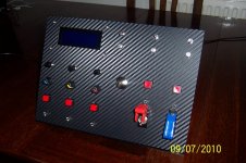
100_1073.jpg One sheet for the panel its self (uncut A4 size) and one more for the floor and sides of the box. Dont forget you can buy the perspex in diffrent colors AND a nice LIGHT tint or CLEAR that is perfect to show displays through (like my LCD display in the panel above).

Next consideration is the controller, I use a Leo Bodnar BU0836 'joystick' USB interface. Its an excellent bit of kit, cheap, very well made and pretty easy to use too! Check it out here :http://www.leobodnar.com/ There are a number of diffrent versions available including a rather more expensive no solder one (But I have a very cheap solution to avoid soldering on the board if you dont like fine solder work!! Keep reading the Tuts:tongue:) and I would recomend the 'Basic' BU0836 here http://www.leobodnar.com/products/BU0836/. This board will cope with not just buttons, but rotary encoders and 'POTS' or potentiometers to give them there propper name lol (thease are whats used to measure the movement in say, your pedals) so it can do lots more than just buttons:cool:

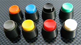
Next up is buttons, this is very much personal taste, the only real requirement is that they are 'Momentary' switches I.E. Press for ON release for OFF (they DONT stay on when you let go) otherwise voltage/ampage is unimportant!:tongue: E-Bay again is favorite for a bargain, but be aware, you get what you pay for! Very cheap buttons/switches tend to be just that, CHEAP n NASTY. A fairly easy way to look at the quality of a switch visually is to look at the body, if its all plastic, its probably cheap and also look at the solder tags where the wires go on, if they are just plastic, again be careful, but if you can see they are 'epoxyed' in place this is a good sign that they are high quality and wont melt the second the soldering iorn goes near them lol!

Again, Leo Bodnar sells excellent quallity switches such as the knitter ones I have used for some of my 'wheel' switches, but at about £8 each, cheap they are not!
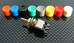
Knitter-MPS103F-caps.pngKnitter-caps-covers.png Top quality knitter switches, easily the best!
board.gifLeo's Bu0836 USB board

Rotary Encoders: Think of these as rotary switches, but digital, only needing 3 wires. The Board see's them as two switches in effect. Turn the knob to the right and it see's it as one button press (i.e button 2 for example that you have 'mapped' for brake bias front) each click you turn to the right, it see's as another 'press' of the button moving the bias further forward. Turn the knob left and its button 1 (mapped for bias rear) Make sense???? Each encoder will use two button inputs. They are pretty cheap and top quality from Leo (I'm not promoting his stuff or on a backhander here lol, just hes got it in stock, right price, will deffo work with his board and good service ) pic below:

CTS288.pngRotary encoder CTS 288 model 288T232R161A2 from Leo Bodnar

Okay, thats about it for part one, lets do a quick recap and parts list:

1) box material: 2x A4 sheets of 3mm thick Perspex
2) controller: BU0836 From Mr Bodnar
3) switches, momentary type

Ask any and all questions on the 'button box' thread and get thinking about your design, type/number of switches, where you want to place them on the panel etc
 
Upvote 0
Right!

A quick part two of the TUT, just to keep you lot on the go lol!

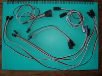
I found these leads on e-bay today for you lot

!Bp2smm!!2k~$(KGrHqQOKiQEuELnVeJLBLtM9+wpEQ~~_35.jpg http://cgi.ebay.co.uk/NEW-10-Servo-...sGames_RadioControlled_JN&hash=item4aa35de28a

Basicaly they are servo extension leads for radio controlled airplanes/cars etc, BUT the female ends fit perfectly onto the USB boards/shift lights that Mr Bodnar sells. They will save you alot of fiddley soldering (wait till you see the supplied plugs that come with the boards). You can get them even cheaper if you order them from a seller in china/H.K. but they will take a couple of weeks to get here. You will only use the female ends of the leads, but still very cheap n easy! Your choise, if your okay with the soldering, save some money......if not, buy these and save some time/burnt fingers and swearing lol!


Next up is marking out! If you guys are using the 3mm thick perspex as I do, it should come with a plastic protective film on both sides, DONT TAKE IT OFF! Not only does it protect the surface from scratches, but it also seems to help stop the saw blade/drill bit from overheating the perspex and melting it! (If it melts, the mess is an unholy one lol)

The best way to plan out your buttons, is to make a cardboard panel (old cereal box is good!) exactly the same size/shape as your planned panel. Bodge it up with some tape/wood or anything so that it will sit on your desk in the planned place (or in the dash etc) and think about if you want it to sit at an angle? Pencil in your buttons, have you got enough clearance for your fingers between the buttons/switches, are they in the right place, is the placing ordered? I.E. when your in the middle of a race, will you be able to reach out and find them without having to look for ages lol? Adjust as nessasary! Take some time with this, yes the Kids and Mrs might think your mad pressing imaginary buttons on a piece of cardboard.........ok, not might, THEY WILL.........but its worth it :tongue:


Once your happy with your placings on the cardboard panel (and the Wife has stopped laughing at you:tongue:) you want to cover the front of the perspex panel in masking tape. This again will help with the cutting/drilling and its MUCH easier to draw on, plus any mistakes can be removed by peeling off that piece of tape and replacing it!

Again, take some time doing this, NOTHING LOOKS WORSE THAN WONKEY, BADLY PLACED, UNEVEN SWITCHES!!!!!!!!! you will be dissapointed if you get this wrong. So if it takes 5 rolls of masking tape, two pens and all your pateince, so be it lol!

When you get to this stage, the fun begins, drilling and FITTING THINGS! :D
 
Upvote 0
Part Three

Okay Guys :D

This part is more of a preparation guide. I'm going to assume your building a replica of my button box pictured earlier in this thread, so just adjust as ness if your is a diffrent size etc:D

Im also assuming that you have finalised you plans, made your panel front and drilled it to suit your buttons/switches (any questions about that, just ask!)

Right before we start on the wiring preps, a quick suggestion: You are going to need to join the bottom and sides of your button box (I will be covering this later) you can use any method you like, but glue is probably the best. I have found that a hot glue gun works really well, it will 'fill' bad joints, makes a solid, strong bond and sets quickly. They are not very expensive, or you may be able to beg/borrow one.........Just a suggestion:cool:

Okay, its MUCH easier to cover your 'panel' fit the buttons etc and wire it BEFORE you assemble/glue it all together, just keep in mind once its covered, thats its more delicate and you need to be careful not to mark/scratch it. I would recomend 3M's Di Noc Carbon film (search e-bay as usual) to cover it if you want it to look like mine. Its a 'Dry' carbon look and pretty impressive. Its self adhesive, all you need to do is make sure your panel is clean and the edges sanded first. Then un-peel the backing and carefully apply the film watching out for air bubbles. Then trim with a scalpel or SHARP hobby knife! Again take your time. Then you can start to fit your buttons/switches. Again, care here, tighten them slowly, use washers so that film does not 'screw up' under the tightening pressure. When its all done, if you got your holes straight and in line and your film on well, it should start to look pretty good! :cool:

Wiring/soldering:

Right, I'm not an electronics Guru lol, so this may not be the correct method for soldering, but its how I do it and it works ok for me........:redface:

For those of you who have not soldered for a long time or EVER, have a PRACTICE on some spare or scrap wire first, using my method if you wish. The first thing to do is to 'TIN' the two components you are joining. This is simlpy applying a light coat of solder on the parts that are gonna be joined. Get your Iorn nice n hot, apply some Flux to the component where you intend to 'tin it. Next place the tip of the iorn to the component, the flux will melt, as it does gently apply some solder to the component, the heat from the iorn should have heated the component sufficently for the solder to melt and if youve done it right the solder should 'spread', quickly remove the iorn. The solder should set looking glossy and smooth. Do this to both components (In this case I'd use two peices of wire), then hold the two components together, apply the iorn again to them, once the solder begins to melt add some more solder quickly and once they have joined remove the heat. Practice this, the quicker you can do this, the less heat is applied to the components, the less likley you will melt something and damage it:wink: If your not sure about anything, ASK ME!

Okay, once we have gotten this sorted its wire up time! DONT FORGET, IF YOUR STUCK ASK ME!:wink:
 
Upvote 0
Sorry for the delay in getting the next part of the TUT done guys, been really busy getting some cool stuff for reviews and GIVE AWAYS for you all and just the general running of the forum! With Kris's help, I should be on track again soon and hope to have the next installment ready in a few days covering the basics of wiring up! Stay tuned and again, sorry for the delay :)
 
Upvote 0

Latest News

How long have you been simracing

  • < 1 year

    Votes: 412 16.4%
  • < 2 years

    Votes: 280 11.2%
  • < 3 years

    Votes: 275 11.0%
  • < 4 years

    Votes: 191 7.6%
  • < 5 years

    Votes: 322 12.8%
  • < 10 years

    Votes: 275 11.0%
  • < 15 years

    Votes: 177 7.1%
  • < 20 years

    Votes: 139 5.5%
  • < 25 years

    Votes: 108 4.3%
  • Ok, I am a dinosaur

    Votes: 330 13.2%
Back
Top