Tutorial - SLI-M Wheel Plate

Hello guys (and gals??),

I thought it might be a nice idea to post a little write up about the little build project me and Brian Clancy did last weekend.
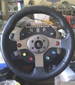
imag0055.jpg

Along the way will be some pictures that i hope you`ll find useful :)

Parts used;

3mm Perspex (Available on ebay)
Carbon Vinyl (3M Di-noc vinyl)
Leo Bodnars' SLI-M ($74.99 or around £49)
Leo Bodnars' Knitter Switches (£6.99 each, plus choice of 8 button colours)
Leo Bodnars' Rotary Encoders (288T232R161A2) (£2.49 each, no knobs)
Rotary Encoder Knobs (£2.25 for 5 incl. postage from HERE)
Servo Extension Leads (£4.37 for 5 incl. postage from HERE)


Obviously the first thing to do was to print off the widely used template from EK for the wheel plate.
However, we noticed that it looked quite small and after some deliberating (and beer & curry), we decided to make it larger.
So here starteth many an hour of photo editing, printing, tinkering and cardboard mock-ups, before finally deciding on a size/design that we were both happy with.

I can't stress enough the importance of cardboard/paper mock-ups of anything you are doing ad-lib, because you can garentee there will be something you hadn`t thought of and there goes all your hours of work and materials bought.

The above process actually took up a whole weekend. BUT, at the end of it, we had a shape and design we were happy with so it was not all time wasted.

As seen and described by other members, the cutting of the perspex can be awkward if your attaching a paper template to it, as it moves around.
I cant really comment on this that much as Brian cut this out for me. However, i have just had a thought occur to me. It might be an idea to aquire some spray adhesive. A quick google search shows that it can be bought from pretty much anywhere, and ranges from £2 to £40!!
I wouldn`t rely on this stuff holding the paper all by itself though, as i doubt its that good. Best to have a back up and keep the template taped down aswell.

EDIT: Be careful with spray adhesives, test then first to make sure they dont MELT the perspex, use sparingly and remember to use on the UNDERSIDE of the board as they will for sure leave a residue that may affect the vynil covering. Also adjust the template acordingly if reversed and not
symetrical :)
 
Once you have the wheel plate cut out, its time to drill your holes.
When it comes to drilling the holes, i guess this is where the spray adhesive would be most beneficial, as the slightest movement of the template here and your holes may as well be bitten out, as they will be useless.

However, in Dans experience, he managed to save his wheel plate expertly (from a print scaling error). See his posts HERE

When you have your plate cut out and your holes drilled, your next step should be to tidy all your edges. The outer edge of your wheel plate can be sanded using fine grades of sandpaper. We found that finalising the edge with a wet and dry grade paper, actually dulled the shiny perspex effect and made it look more like carbon, especially after the vinyl was attached.

The vinyl itself is actually quite easy to attach, as it is rigid enough not to crease easily. This rigidity also helps to hide any imperfections, not that we had any!! lol
Instead of trying to cut the vinyl to shape, THEN fit it to your plate. Your best bet would be to cut it slightly larger than the wheel plate and then trim it to size.

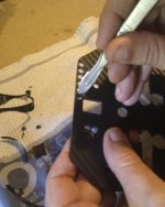
Here is a picture of the holes being cut;

imag0033.jpg

Using a very sharp scalpel makes this job very easy, but also very dangerous lol. Be VERY careful with these knives, as they are truely sharp.
As Brian explained to me, he found the best way to cut out the holes was to 'stab' the vinyl through the hole from the reverse (un-vinyl'd) side of the wheel plate, then turn it over and cut at an angle so that it kind of tapers into the hole. Best way to describe it is so that there is no overhang of vinyl over the hole.
The same applies to the outer edge, as the last thing you want is to catch the vinyl at the edges and it start to peel.

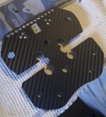
And here's one i prepared earlier......

imag0034.jpg

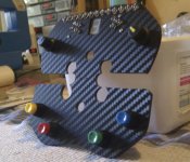
Here you can see we've placed the SLI-M to see how it looks against the carbon vinyl. And the result is it looks pretty damned nice.
The keener eyed modders of you may have noticed that the top and bottom of the 6 holes for the wheel 'bolts' are smaller than they should be (13mm). This is because we didnt have a 13mm drill bit and couldn`t easily widen these, so we cheated.
These holes need to be 13mm to accommodate the shafts of the plastic 'Logitech' branded wheel centre. But instead, we trimmed those shafts so they were flat. And that is how we got away with having those holes abit smaller.
Why dont you do that with all the holes you ask?? Good question...... You see, if you did that, the wheel plate would have nothing to line up with, so when you came to bolt the wheel over it, it would slide about until all the bolts were tightened. Even then, with a hard enough knock, it would move. So just doing this to two of the shafts was ok (but voids the warranty, so please be advised).

EDIT: Errr, actually, just undoing the bolts voids your warranty, so do consider this BEFORE you start a project like this!
 
Upvote 0
If you intend on using the encoder knobs listed above with Bodnar's rotary encoders, then be aware that you will have to do some preperation to both items.
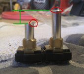
The shafts of the rotary encoders will need to be trimmed by roughly half of its original length. This is a ball park figure as you can change this to alter how high you want the encoder knob to sit.
Here is a picture of before and after;

imag0036.jpg

Highlighted in green is the difference between the two shaft lengths. As you can see its roughly half. The red circle on the cut shaft shows a little bit of swarf (leftovers) from using a hacksaw to cut it. So the next part will be to file it down to resemble how it used to look (the red circle on the un-cut shaft). What we are aiming for here is a flat top and slightly taper the edge so that the knob goes on easily.
Your next step will be to 'ream' the encoder knob itself. If you try to fit the encoder knob on before doing this, you will see that it will not fit. The encoder shaft is larger in diameter than the encoder knobs 'hole'. If you use a 6.5mm drill bit turned by hand, you can get a nice snug fit if done properly.

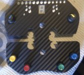
When it comes to fitting the switches/rotaries, take your time and be careful. The last thing you want to do after all this work is scratch your carbon vinyl.
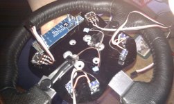
Take note as to what position the pins are at the back. Using abit of common sense, be aware of wire placement etc. when the wheel plate is fully mounted. It may be a good idea to attach the wheel plate and wheel and have a look at how much room you have. Just to give yourself an idea of the space you have to work with.

When your done, you should end up with something like this;

imag0043.jpg imag0048.jpg

You're just about ready to start soldering now, so make sure you have your flux and a wet sponge at your fingertips.


To Be Continued.......
 
Upvote 0
..... Continued

With all your soldering equipment ready and everything in front of you, what you should be planning to do is 'Tin' all the connections you plan on soldering.
What this means is to have a layer of solder on the contact points already, so that when you come to join/solder them, it makes it much easier for them to stick, as all you need to do is hold them together and heat the connection lug on the switch so the solder melts together.

If you require further info or techniques on soldering, Brian Clancy is the man to speak to.

Wiring the rotary switches will require one set of cables per switch. So they, technically, are the easy ones to do.
If you buy the servo extension cables, then you will be soldering the black and white cables to the OUTER lugs in the switches. The red is the earth and should be soldered to the CENTRE lug. (see pic below)

imag0052.jpg

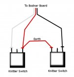
When you come to do the knitter switches, you can wire two of them through one set of cables.
Looking at the crude diagram, you can see that the centre lug is NOT used on the knitter switches. Based on you using the servo extension leads, you need to solder the white wire to an outer lug on 'switch X' and the black wire to an outer lug on 'switch Y'. The red wire can be soldered to either switch X or Y, as long as you add a small length of wire to 'bridge' the two switches.

Diagram.jpg

If none of this makes any sense, dont worry, your not alone.
There are plenty of people here to answer your questions, so dont be shy, ask what ever you need to.


To be continued.........


By the way..... this thread is locked so this all stays together. When i have finished the write up, it will be open for discussion.
Sorry if this causes any inconvenience.
 
Upvote 0

Latest News

How long have you been simracing

  • < 1 year

    Votes: 348 15.5%
  • < 2 years

    Votes: 241 10.7%
  • < 3 years

    Votes: 241 10.7%
  • < 4 years

    Votes: 177 7.9%
  • < 5 years

    Votes: 299 13.3%
  • < 10 years

    Votes: 257 11.5%
  • < 15 years

    Votes: 165 7.4%
  • < 20 years

    Votes: 125 5.6%
  • < 25 years

    Votes: 99 4.4%
  • Ok, I am a dinosaur

    Votes: 291 13.0%
Back
Top