SFX100 direct drive belt tensioner

I’d like to show you a direct drive belt tensioner which can be mounted at the back of the SFX100 actuators. You can build this yourself, see the attached manual. Also attached is the STL which you can use to 3D print the tube bearing holders. I’m using Saxxon’s excellent SimFeedback software to control the tension of the belts, the same way as it controls the actuators. All information is in the manual.
Note 1: due to the size of the manual I had to split the PDF into three files - page 1 to 18, 19 to 25 and page 26 to 36.
Note 2: rename "Bearing holder.stl.txt" to "Bearing holder.stl".

20200414_101258.jpg
20200412_142546.jpg
20200424_142709.jpg
20200414_101346.jpg


Update: I have added the waist (hip) belts to the tube as well. This improves the feeling a lot! Highly recommended.

1.jpg


2.jpg


Rolled off:

4.jpg


Rolled up:

5.jpg


I have mounted a bigger plate:

6.jpg


The servo has a lot more work to do, so I had to increase the torque limit (P8 / P9) from 75 to 200.

Update 11/11/2020. Version 1.2 of the manual:
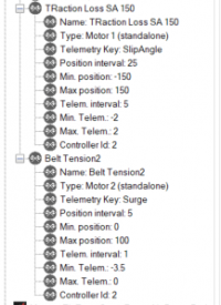
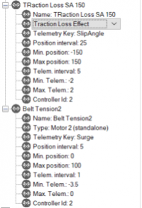
  • There was an error in the screenshot of the SimFeedback AC profile: “Type: Pitch Effect” should be “Type: Standalone Motor 1”. Thanks to Metalnwood for pointing that out to me. This also has the advantage of not having to wind the belts manually before starting SimFeedback.
  • Changed servo drive parameter P97 to 0 so it winds the tube as shown in the pictures.
  • Added a section about adding hip belts (highly recommended!).
  • Changed the servo drive configuration and safety warning.
  • Added a few lines on how to setup the belts for the first time.
 

Attachments

  • Bearing holder.stl.txt
    196.8 KB · Views: 451
  • Construction manual belt tensioner V1.2 page 1-18.pdf
    1.8 MB · Views: 594
  • Construction manual belt tensioner V1.2 page 19-25.pdf
    990.6 KB · Views: 375
  • Construction manual belt tensioner V1.2 page 26-36.pdf
    1.7 MB · Views: 513
Last edited:
To me it seems that a 750W motor is a bit much for a belt tensioner, I've seen other projects that use far less ( < 300W) and still don't run 100% of strength. As I don't have an SFX-100 (yet..), could you maybe shed some light on the costs to create this tensioner? Because those motors with controllers are pretty pricey, especially to ship (Europe) and with extra customs, it seems a bit much for a single-motor tensioner.
I'm trying to decide between i.e. the SimXperience G-Belt system (also expensive to import) and a DIY solution, but find it a difficult decision.

To make it even more expensive, have you thought about a two-motor setup for your project?
 
Last edited:
Upvote 0
To me it seems that a 750W motor is a bit much for a belt tensioner,
I've seen other projects that use far less ( < 300W) and still don't run 100% of strength.
A pair of hobby servos, both consuming less than 40W peak, can suffice.
More powerful motors should employ correspondingly reduced mechanical leverage,
e.g. using larger diameter tensioning rollers on motor shafts, to avoid injury risk.
Larger diameter also increases effective tension slew rate, provided rollers are not massive.
 
Upvote 0
Hi @Insert Coin ! Thanks for this guide! Ordering parts now, one thing that’s not super clear to me is, how do you determine the length of the tube. You mentioned that in your case it was 63cm, but without the motor and mounts in hand, is there a way to calculate the distance? How wide is the distance (center to center, or inner to inner) of your sfx actuators? I have a p1-x and my center to center is 68 cm.

Also I do not have access to the discord (as I understand it’s behind a pay-wall, and my sfx is customized) where the roller stls are. I was going to get creative and devise my own in fusion, unless you were able to somehow get those files for me.

Again thanks for the detailed guide. This should be a snap after I get this measurement. What are your feelings / tips / “wish-I-would-haves” after having the setup for a bit now?
 
Last edited:
Upvote 0
Wow, first off, love the colors, @DJ_Psymon! how did you get the sfx to “pull”? Any mods to the internals? I would think that the force of the seatbelt tightening would pull the main tube out of the slider.
 
Upvote 0
Hi @Insert Coin ! Thanks for this guide! Ordering parts now, one thing that’s not super clear to me is, how do you determine the length of the tube. You mentioned that in your case it was 63cm, but without the motor and mounts in hand, is there a way to calculate the distance? How wide is the distance (center to center, or inner to inner) of your sfx actuators? I have a p1-x and my center to center is 68 cm.

Also I do not have access to the discord (as I understand it’s behind a pay-wall, and my sfx is customized) where the roller stls are. I was going to get creative and devise my own in fusion, unless you were able to somehow get those files for me.

Again thanks for the detailed guide. This should be a snap after I get this measurement. What are your feelings / tips / “wish-I-would-haves” after having the setup for a bit now?
I'm not near my rig at the moment, but since the tube sticks out you can leave it much longer and cut it later (when you have assembled it).
The STLs are attached to the first post, just rename them to .stl.
I don't have any wishes or tips, I'm still very happy with it and haven't changed a thing.
 
Upvote 0
Wow, first off, love the colors, @DJ_Psymon! how did you get the sfx to “pull”? Any mods to the internals? I would think that the force of the seatbelt tightening would pull the main tube out of the slider.
The the internal parts need replacing. Don't want to steal this thread so I'll start another post once I got everything tested working correctly.
 
Upvote 0
Los archivos STL de los rodillos se pueden encontrar en el canal de Discord del tensor de cinturón de SimFeedback (consulte la parte superior de ese canal y los mensajes fijados).

Aquí hay algunas fotos más de los rodillos superiores:

View attachment 384124

View attachment 384126

View attachment 384128

View attachment 384129

La parte media está pegada a su base y también atornillada a la base como puedes ver en la foto. La base en sí está unida a la silla con velcro industrial 3M (se puede ver un poco del velcro debajo de la base), no taladré mi silla. Consejo para el uso del velcro industrial 3M: pégalo en la base y en la silla, presiónalo manualmente y déjalo durante 24 horas. No lo presione, simplemente déjelo reposar durante 24 horas. Luego colóquelo en la silla. Es muy fuerte.
Podría compartir tus archivos STL, no puedo encontrarlos en discordia
 
Upvote 0
HI Ya, I have my Belts working (similar setup to yours) plus traction loss, my problem is traction loss is affecting the belts. (without braking when traction loss comes on the belts tighten??) if I disable traction loss all is fine with the belts. both TL and Belts are on the second Arduino Belts using Motor 2, TL using Type:Traction loss (also tried Type: Motor 1) as per screenshot. Any ideas??
 

Attachments

  • image (1).png
    image (1).png
    45.2 KB · Views: 60
  • image.png
    image.png
    37.1 KB · Views: 55
Upvote 0
HI Ya, I have my Belts working (similar setup to yours) plus traction loss, my problem is traction loss is affecting the belts. (without braking when traction loss comes on the belts tighten??) if I disable traction loss all is fine with the belts. both TL and Belts are on the second Arduino Belts using Motor 2, TL using Type:Traction loss (also tried Type: Motor 1) as per screenshot. Any ideas??
No idea, sorry (I don't have traction loss).
 
Upvote 0

Latest News

How long have you been simracing

  • < 1 year

    Votes: 358 15.7%
  • < 2 years

    Votes: 252 11.0%
  • < 3 years

    Votes: 243 10.7%
  • < 4 years

    Votes: 179 7.8%
  • < 5 years

    Votes: 302 13.2%
  • < 10 years

    Votes: 260 11.4%
  • < 15 years

    Votes: 166 7.3%
  • < 20 years

    Votes: 128 5.6%
  • < 25 years

    Votes: 99 4.3%
  • Ok, I am a dinosaur

    Votes: 294 12.9%
Back
Top