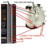
Rotary Encoder + Leo Bodnar Wiring!

What you have purchased, according to your link, is a rotary switch not a rotary encoder.
A rotary encoder only puts out two signals, one when turned clockwise and a different signal when turned anti-clockwise. They have no limit on the revolutions it can turn in both directions.
They are used for brake bias, volume control etc.
Basically if you want to control something that has two inputs, left - right, increase - decrease, front - rear.

A rotary switch is used for switching between different functions.
They generally have 12 switch positions but with the use of a supplied stopper you can limit the amount of positions it can be rotated.
You could use a rotary switch for selecting the different HUD LCD screens in rFactor or the black boxes in iRacing etc.

As for wiring that rotary switch to the BBI-32, there would be one ground contact, in the centre of the switch, that would go to a ground contact of the BBI-32.
Then depending on how many switch functions you want, one wire from each switch terminal goes to a numbered terminal on the BBI-32.

Leo Bodnar has his own rotary switches that only require 2 wires for the 12 switches instead of 13 wires for your rotary switch.
 
Upvote 0
great thank you very much so i will do that then, i bought this because i will use this rotary switch to change the layout on the phone witch i use t see diferent infos, its RS Dash, so for now the app has about 6-7 layout, and maybe in the futre they will add more.

i thought at one point to do what you juust told me buut wasnt sure, but thnx anyways:)
 
Upvote 0
alright so i have a problem,

i soldered i wire to each of the 13 pins in the bottom withch represent 13 button ''presses'', and & wire to the ground.
So if youu know the BBI-32 board, there is B1-GRND, B2-GRND,etc
The problem i have now is that the only button witch will work is the one with the ground wire, the others dont work.

so, if i run another wire from every pin to the ground and then to the two pins in the leo bodnar board, would that solve the problem?
 

Attachments

  • wiring example.jpg
    wiring example.jpg
    33.5 KB · Views: 929
Upvote 0
If I follow the diagram correctly, you've wired the ground on the switch to each of the pins on the switch and then ran two wires from each of those to +ve & ground?

You only need to run one wire from each pin on the switch to the +ve pads and then you can just run a single wire from the ground on the switch straight to one of the grounds on the board. It uses a common ground so you don't need the 13 ground wires.
 
Upvote 0

Latest News

How long have you been simracing

  • < 1 year

    Votes: 356 15.6%
  • < 2 years

    Votes: 250 11.0%
  • < 3 years

    Votes: 243 10.7%
  • < 4 years

    Votes: 178 7.8%
  • < 5 years

    Votes: 302 13.3%
  • < 10 years

    Votes: 260 11.4%
  • < 15 years

    Votes: 166 7.3%
  • < 20 years

    Votes: 128 5.6%
  • < 25 years

    Votes: 99 4.4%
  • Ok, I am a dinosaur

    Votes: 293 12.9%
Back
Top