Logitech G25, G27, G29, G920 load cell DIY project

Seeing that I haven’t completed the work, allow me to showcase the work of others in my place, as this is starting to become more of a repository of ideas on the topic.

RD member GeekyDeaks showcases a bathroom scale based load-cell project on his github
- More details about bathroom scale based loadcells

RD member Grezson built one by using a 20kg straight Bar load-cell (which are very cheap btw)
- More details about straight bar based loadcells not specific to logitech

- More general information about load-cells
- Some older research completed that is still relevant

- RD member Panicpete has also shared a lot of detail about his own project that can be found on this thread

Provided in the spoiler below is all the most pertinent information I’ve dug up on building a button load-cell for the Logitech brake pedal. Very similar in design to that of Richmotech’s model. The total cost for this project would come around $60 to $70 on the low end roughly. Be advised, I’ve not actually completed this project and ended up installing the AXC Sim brake mod in it’s place, which comes at the same cost it would take to build a button load-cell mod.
Parts list:

Steel Spring:

30mm Outer Diameter (This is wrong, I will updated the O.D. and I.D. later)
2.0mm Wire Diameter
50mm length
A length of 50mm is overshooting it, so the spring would need to be shorten to length with a dremel. A dual rated spring such as what is used with the nixim and gteye mod might also work, but I presume that having a combination of the spring, rubber and the load cell should provide for enough change in pressure. I've also read of some success by using a product called Real Pedal that can be found on ebay, which comes with a spring and sponge, but a bit over priced again at $30. So best to DIY this imo.


3123_0.jpg

Load Cell
The load cell should have an Outer Diameter or 25mm and not likely much larger, but definitely not greater than 28mm. The Logitech housing that holds the spring assembly has an inside diameter of 30mm, so it needs to be a bit less than that. The actual rating of the load cell should be around 45kb (100lbf) and a 3 wire system that can be supplied with up to 5V.

Example load cell:
Button Load Cell (50kg) - CZL204E
FC22 Compression Load Cell (45kg)
note: This particular model would need to have the mounting brackets edged off with something like a dremel.


Amplifier:
An amplifier might not actually be needed if the supplied voltage is maintained, but they are pretty cheap and might be a good fail safe to have. An affordable standalone load cell amplifier by Leo Bodnar or maybe something like a SparkFun Load Cell Amplifier - HX711. Can't really say for sure what the best option is just yet.
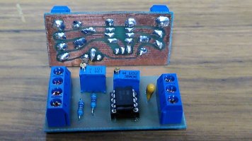
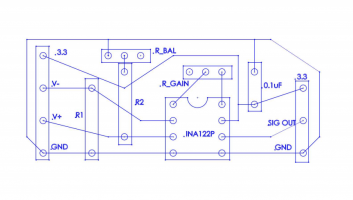
OR build your own:

Rubber fuel line:
This should have an outsider diameter that doesn't exceed the insider diameter of the steel spring (possibly a hair shorter to be on the safe side) and then just trim it up to fit inside the spring.

Felt or Foam:
To wrap around the load cell so as to make a more snug fit.

For assembly, simply refer to any Ricmotech style information, such as,
Sim Racing Garage review
Ricmotech assembly manual
 
Last edited:
Geez, i can't believe i messed up the layout again!
You probably have some way to go before you hit my tally :D

Got one more INA122 and figured i'd hook it up to a breadboard before soldering everything together
This is great. I started to watch the video and spotted one thing straight away though. The pot doesn't seem to be connected at all.

You seem to have already figured out the direction of the tracks in the breadboard as you have connected up the pins of the INA122 using them, but I think you got them mixed up when you installed the pot as you have both the wires to the right of the pot on the same track and the pot has all it's pins on one track too.

Just as a reminder, here is the direction of the tracks:

1612345105608.png


But... this should give you a gain of x10000, so I think there is still something else wrong too.

So, first thing is that the wiring looks ok, but I cannot quite tell the orientation of the INA122 from the video. Can you take a photo of the breadboard that clearly shows the markings on the chip?

Let's do the diags with the multimeter. I'd like to start with just measuring the voltage out of the amp using the 4 wire load cell for simplicity
 
Upvote 0
@Pubwie - I just realised that the way you are testing the bathroom scale load cell will probably not work as intended.

I never figured out exactly why, but when you just try and press the large flat part, it causes both resistances to change in the same direction. You have to apply the load to the small bridge connecting the smaller arms and ensure that the cell is properly supported on the outer metal rim. This then causes one of the resistances to increase and the other to decrease.


EDIT: also, when you swapped the cells in the vid, I could not tell if you had the 1K resistors making up the other half of the bridge.

Either way, let's keep it simple to begin with and use the multimeter and the bar load cell

1. can you take a photo of the breadboard showing the markings on the chip clearly so we can verify your wiring
2. find a way to mechanically clamp one side of the bar load cell so that you can apply a reasonable amount of force to it. If you have something like a luggage scale, try using that on the other end so you can verify you are able to apply > 10kg
3. check the voltage between pins 7 and 5 is approx 5v
4. check the voltage between pins 7 and 4 is approx 5v
5. check the voltage between pins 2 and 4 is approx 2.5v
6. check the voltage between pins 3 and 4 is approx 2.5v

EDIT2: if you are not familiar with how a load cell works, I recommend reading up on how a wheatstone bridge works. It's a simple trick to allow measurement of very small differences of large resistances. An analogy I use is to imagine that you want to accurately measure the difference between two 10m bars to 0.1mm. Using something like a vernier is not going to work across the whole length of either bar, but you can put them side by side and use the vernier to measure just the difference between the two. You still don't know accurately what the length of either one is, but you can accurately tell what the difference is. The wheatstone bridge is doing the same thing. It's measuring the slight differences in the large resistors that are part of the load cell and which change by small amounts under mechanical stress
 
Last edited:
Upvote 0
You seem to have already figured out the direction of the tracks in the breadboard as you have connected up the pins of the INA122 using them, but I think you got them mixed up when you installed the pot as you have both the wires to the right of the pot on the same track and the pot has all it's pins on one track too.

AH!
I had a feeling the POT was not right in some way! Thank you!!

2. find a way to mechanically clamp one side of the bar load cell so that you can apply a reasonable amount of force to it. If you have something like a luggage scale, try using that on the other end so you can verify you are able to apply > 10kg
Will have to do this one tomorrow with some more tools.


1. can you take a photo of the breadboard showing the markings on the chip clearly so we can verify your wiring
I believe this is as you mentioned before, pin 6 goes to A0 on Arduino.
Model number facing downward + Indent facing to the left, which to my understanding means pin 1 should be as shown here (left/bottom)
Breadboard - INA122pa orientation -jpeg.jpg


These troubleshooting tips are great, though I'm not sure if something is going on with the INA122..
With Arduino providing power, I did the 2 sets of measurements with the VCC and GND on both pin 7 and 8.
A)
VCC – Left (red)
GND – Right (black)

1. VCC  left red + GND right blk- jpeg.png

1. check the voltage between pins 7 and 5 is approx 5v = 4.85
2. check the voltage between pins 7 and 4 is approx 5v = - 4.85
3. check the voltage between pins 2 and 4 is approx 2.5v = 0.00
4. check the voltage between pins 3 and 4 is approx 2.5v = 0.00

B)
GND – Left (black)
VCC – right (red)

2. GND left blk+ VCC right red - jpeg.jpg

1. check the voltage between pins 7 and 5 is approx 5v = 1.74
2. check the voltage between pins 7 and 4 is approx 5v = 1.64
3. check the voltage between pins 2 and 4 is approx 2.5v = -1.10
4. check the voltage between pins 3 and 4 is approx 2.5v = -0.83

EDIT: also, when you swapped the cells in the vid, I could not tell if you had the 1K resistors making up the other half of the bridge.
Not sure about the bridging :/
Do you mean the wiring splitting and connected to resistors?
50kg 3 to 4 wire resistor wiring - jpeg.jpg
 
Upvote 0
First of all, the wiring on the Arduino side is without ambiguity: Pin 7 goes to VCC, pin 6 goes to A0 (or any other analog pin on the arduino), and pins 4 and 5 go to GND (you could also connect pin 5 to VCC if you want to invert the output, but lets keep it simple for now). No need to switch the wires around on that side.

Some things I can tell from the pictures you provided:
  • The orientation of the INA122 looks ok to me and the pin numbering should be correct.
  • In the second picture, you have connected the black wire of the load cell to pin 1. That wire should be connected to either GND or VCC. I think you had it right in your video.
  • The wiring diagram in the last picture can't be correct. Assuming the color coding of your load cell is the same as mine (red=signal, black/white = GND/VCC), then the resistors are correct, but the white and red wire to the board should be swapped (this is really confusing, as for the 4-wire load cells, red actually is the VCC and not the signal wire). Also note, that the used resistors should be matched as closely as possible, preferably from the same production batch.
But as GeekyDeaks suggested, let's focus on getting the 4-wire load cell working first.

I would recommend to always use the black wire on the load cell as GND to avoid further confusion (as the load cells themselves don't have polarity, you could also connect it to VCC). Then, for the 4-wire cell, connect the red wire to VCC. The two signal wires (white/green) go to pins 2 nad 3 of the INA122, here you might have to switch around to find the right configuration.
 
Last edited:
Upvote 0
First of all, the wiring on the Arduino side is without ambiguity: Pin 7 goes to VCC, pin 6 goes to A0 (or any other analog pin on the arduino), and pins 4 and 5 go to GND (you could also connect pin 5 to VCC if you want to invert the output, but lets keep it simple for now). No need to switch the wires around on that side.

Some things I can tell from the pictures you provided:
  • The orientation of the INA122 looks ok to me and the pin numbering should be correct.
  • In the second picture, you have connected the black wire of the load cell to pin 1. That wire should be connected to either GND or VCC. I think you had it right in your video.
  • The wiring diagram in the last picture can't be correct. Assuming the color coding of your load cell is the same as mine (red=signal, black/white = GND/VCC), then the resistors are correct, but the white and red wire to the board should be swapped (this is really confusing, as for the 4-wire load cells, red actually is the VCC and not the signal wire). Also note, that the used resistors should be matched as closely as possible, preferably from the same production batch.
But as GeekyDeaks suggested, let's focus on getting the 4-wire load cell working first.

I would recommend to always use the black wire on the load cell as GND to avoid further confusion (as the load cells themselves don't have polarity, you could also connect it to VCC). Then, for the 4-wire cell, connect the red wire to VCC. The two signal wires (white/green) go to pins 2 nad 3 of the INA122, here you might have to switch around to find the right configuration.

Thanks!

With the 4 wire cell wired up as suggested the voltage readings look more like the approximations, GeekyDeaks mentioned before, except for when the white loadcell wire is connected to pin 3 or 2.
The reading on pin 3 and 4 is a bit low = +- 1.4V
Will have to show in another vid next week.

In anycase, still no reading on the PC though, even after swapping green/white loadcell wires between INA122 pin 2 and 3.

Forgot solder today, so will have to match the resistors on the 3 wire cell next week and try again.

Fingers crossed.
Thanks for taking the time!
 
Upvote 0
With the 4 wire cell wired up as suggested the voltage readings look more like the approximations, GeekyDeaks mentioned before, except for when the white loadcell wire is connected to pin 3 or 2.
The reading on pin 3 and 4 is a bit low = +- 1.4V

That seems odd. Could you measure the resistances across the load cell wires to make sure it is intact?
Assuming it is using 1k resistors internally, you should get:
VCC to GND (black to red): 1k
Signal to signal (white to green): 1k
any other combination: 750 Ohms

Your absolute values might be different, but the proportion should be the same (identical resistance GND to VCC and signal to signal; 75% of that for the other combinations).
 
Last edited:
Upvote 0
The reading on pin 3 and 4 is a bit low = +- 1.4V
Sorry, have been busy with work and only just got around to looking at this. I agree with @Panicpete, this seems odd and you should verify the resistances in the loadcell between the wires to determine it's internal configuration.

I suspect that the 1.4v is because you have connected the Vcc and Gnd across just one resistor and so the other outputs are now from the connections between the remaining 3 resistors. With a load of 4.8v, you are going to get about a drop of 1.6v across each one, so 1.4v is a little low but it's my best guess at present
 
Upvote 0
Thanks GeekyDeaks.
great design, works brilliantly!

finished my load cell mod today.
I reworked the layout a little to make it easy to etch and solder by hand
total cost per board was less than AU$25ea including an etching kit to make 4 boards.

add in a little 3d printing, and a couple of pencil erasers, and it feels like the real thing.

cheers
honky
 

Attachments

  • 175889290_2982204082059449_4471430970271298368_n.jpg
    175889290_2982204082059449_4471430970271298368_n.jpg
    178.2 KB · Views: 664
  • 176265341_1679796258871275_2591863920971814041_n.jpg
    176265341_1679796258871275_2591863920971814041_n.jpg
    157.8 KB · Views: 422
  • 176153964_721881701784701_1608108575410285870_n.jpg
    176153964_721881701784701_1608108575410285870_n.jpg
    214.9 KB · Views: 429
  • 176297048_822100361985728_3278378616104169163_n.jpg
    176297048_822100361985728_3278378616104169163_n.jpg
    96.1 KB · Views: 494
  • 174192850_473987660723351_318324755353726956_n.png
    174192850_473987660723351_318324755353726956_n.png
    144.9 KB · Views: 537
  • 174818797_293317809081954_5835764435211075843_n.png
    174818797_293317809081954_5835764435211075843_n.png
    31.1 KB · Views: 442
Upvote 1
Hi. I've been reading all sorts of information about creating an affordable, simple, sub 30 EUR solution for creating a more realistic feel for the G29 brake pedal. The load cell idea seems like the ideal solution, though still quite expensive with quite a bit of parts when introducing the amp.

Here's a crazy idea. How about using a syringe of an appropriate size that fits inside of the brake pedal spring housing. Inside of the syringe sits the spring. On top of the syringe, a 3.3v pressure sensor is used of the appropriate input and output voltage. Though the working principle of this idea is completely different from load cells, I believe it could produce a good result. Some issues I've considered are whether or not a syringe can hold enough pressure for something like this, and the issue of connecting a syringe to a pressure sensor.

I might give this a go and hack something working up.
 
Upvote 0
Wow, those 3D print files from GeekyDeaks were exactly what I needed!
I am planning to switch to a DD wheel, but have not decided on what pedals to use.
That's why I decided to modify my G27 pedals to work standalone using an Arduino Pro Micro compatible microcontroller (11€ on Amazon) with the help of a youtube video, and I also got those exact bathroom load cells with the HX711 board that GeekyDeaks suggested. I used another youtube video to wire this to the microcontroller as well.
Now, I can use the pedals with a USB cable, either normally or with a load cell. However, I was still missing a good way to mount the load cell, but now I will try the 3D prints and see how those work.
I will post my whole pedal modifications and the microcontroller software once I got it 3D printed!
 
Upvote 0
Thanks GeekyDeaks.
great design, works brilliantly!

finished my load cell mod today.
I reworked the layout a little to make it easy to etch and solder by hand
total cost per board was less than AU$25ea including an etching kit to make 4 boards.

add in a little 3d printing, and a couple of pencil erasers, and it feels like the real thing.

cheers
honky
Hey man... I know it's more than a year, but may I ask about the value and orientation of those transistors? I've been trying to copy the design you have here and I *kinda made it work. The BALANCE knob works but the GAIN knob doesn't. Also, When I get it to full off state, nothing happens when I press the module. It only kinda works if the bar is *floating in the middle and then I can see the load cell moving up and down when I press it.

I used 1k transistors and 100nf caps with 104 markings. I am also using a three-wired load cell with the full-bridge transistor conversion if that helps. Thanks in advance!
 
Upvote 0
Hey man... I know it's more than a year, but may I ask about the value and orientation of those transistors?
I think you might mean the resistors? If so, they should be 1k ohm, however there is usually quite a big tolerance to most resistors, so I'd recommend getting a few and measuring which ones are closest as it's more important that they are nearly the same value. You want to use the one that is slightly larger with the 10 ohm balance pot. Orientation doesn't matter.

Also, When I get it to full off state, nothing happens when I press the module
That sounds like the G29 is calibrating to the highest voltage it will accept and then there is not enough of a voltage change when applying load.

The calibration process is a bit of a PITA because the G29 is inverted. i.e. around 3.1v is 0% brake and 1.6v is 100% brake (approx).
What I would suggest is starting at the amp input side. Check the voltage between pins 2 and 3 at rest and under load. You should see something at rest under 10mv, but what you are aiming for is that the voltage under load is 1/2 that when at rest. This really determines how hard you want the pedal to feel and it's what the balance pot is for tweaking. for example, if you tweak the balance pot to have 6mv at rest and under a comfortable load you get about 3mv, you are good to go. (if the mv goes up under load, you need to swap the load cell white and black wires around)

Once you have the input working ok, then you can tweak the gain to get it so that you have about 3.0v - 3.1v at rest and check it goes down to about 1.5 - 1.6v under load.

The next stage then is probably the fine tuning. You can adjust the balance to make the pedal feel easier or harder, but you then need to adjust the gain to set the rest level.

Good luck!
 
Upvote 0
I think you might mean the resistors? If so, they should be 1k ohm, however there is usually quite a big tolerance to most resistors, so I'd recommend getting a few and measuring which ones are closest as it's more important that they are nearly the same value. You want to use the one that is slightly larger with the 10 ohm balance pot. Orientation doesn't matter.


That sounds like the G29 is calibrating to the highest voltage it will accept and then there is not enough of a voltage change when applying load.

The calibration process is a bit of a PITA because the G29 is inverted. i.e. around 3.1v is 0% brake and 1.6v is 100% brake (approx).
What I would suggest is starting at the amp input side. Check the voltage between pins 2 and 3 at rest and under load. You should see something at rest under 10mv, but what you are aiming for is that the voltage under load is 1/2 that when at rest. This really determines how hard you want the pedal to feel and it's what the balance pot is for tweaking. for example, if you tweak the balance pot to have 6mv at rest and under a comfortable load you get about 3mv, you are good to go. (if the mv goes up under load, you need to swap the load cell white and black wires around)

Once you have the input working ok, then you can tweak the gain to get it so that you have about 3.0v - 3.1v at rest and check it goes down to about 1.5 - 1.6v under load.

The next stage then is probably the fine tuning. You can adjust the balance to make the pedal feel easier or harder, but you then need to adjust the gain to set the rest level.

Good luck!
Thanks man... I have limited knowledge regarding electronics. I'm using a G27 BTW and I don't have a tester on hand. I just read the labels etc. I guess it's never too late to learn new things eh? Thanks again for the quick reply. Cheers!
 
Upvote 0
Thanks man... I have limited knowledge regarding electronics. I'm using a G27 BTW and I don't have a tester on hand. I just read the labels etc. I guess it's never too late to learn new things eh? Thanks again for the quick reply. Cheers!
Ah, the G27 might run at 5v. If so, just bear in mind that the output from the amp will likely be more in the 2.5 - 5v range
 
Upvote 0

Latest News

How long have you been simracing

  • < 1 year

    Votes: 88 12.6%
  • < 2 years

    Votes: 63 9.0%
  • < 3 years

    Votes: 72 10.3%
  • < 4 years

    Votes: 44 6.3%
  • < 5 years

    Votes: 98 14.0%
  • < 10 years

    Votes: 96 13.7%
  • < 15 years

    Votes: 60 8.6%
  • < 20 years

    Votes: 40 5.7%
  • < 25 years

    Votes: 33 4.7%
  • Ok, I am a dinosaur

    Votes: 105 15.0%
Back
Top