So... As I said before, this is almost a subjective theme. I have no experience with racing cars and with sport street cars. The only gear shift I have played in recent times, was a Mustang new Gen. And the engagement/disengagement was different. If I remember correctly, it was harder to disengage then to engage. And using logic, it makes more sense to make it harder to disengage then to engage. It will be worst to "pop out" by accident the gear out, then to make harder to engage.
I have as well some pics to make my argument:
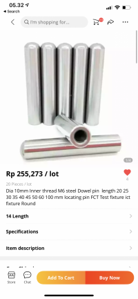
This are the shifter rod (or shaft), connected to the forks. Normally a gear box have 3 to 4 rods. One for a pair of gears. So, 1st and 2nd; 3rd and 4th; 5th and 6th. And normally they have notches were the Detent ball rolls on (not all gearboxes are equal...).
Mazda MX5 6 speed gearbox.

Tremec gearbox from a Mustang (don´t know the version, but is not the latest model)

And, the odd ball; JEEP gearbox
.jpg")
Unfortunately is hard to find good pics about this subject. But, as you can see, all the notch are asymmetric and easier to engage and hard to disengage.
I have a really nice pdf from LUK company about detent balls. if you are interested to see, here it is:
 drive.google.com
This is why I designed the slops like this.
Hope this info is correct and helpful. And I would love to have more info about this subject. If any of you have something to share, please feel free!
I have as well some pics to make my argument:
This are the shifter rod (or shaft), connected to the forks. Normally a gear box have 3 to 4 rods. One for a pair of gears. So, 1st and 2nd; 3rd and 4th; 5th and 6th. And normally they have notches were the Detent ball rolls on (not all gearboxes are equal...).
Mazda MX5 6 speed gearbox.
Tremec gearbox from a Mustang (don´t know the version, but is not the latest model)
And, the odd ball; JEEP gearbox
Unfortunately is hard to find good pics about this subject. But, as you can see, all the notch are asymmetric and easier to engage and hard to disengage.
I have a really nice pdf from LUK company about detent balls. if you are interested to see, here it is:
SHIFT_DOCS - Google Drive
drive.google.com
This is why I designed the slops like this.
Hope this info is correct and helpful. And I would love to have more info about this subject. If any of you have something to share, please feel free!
Last edited:


") Of course it takes a lot force to disengage a gear when the clutch is not pressed, but that is not how you change gear.
Of course it takes a lot force to disengage a gear when the clutch is not pressed, but that is not how you change gear.