Help in choosing the right board for a wheel project

Hello everyone! I decided to design my own wheel and I'm trying to understand the diferences in Arduino models for what I need. At first I was decided on using a Mega 2560 as it had a lot of pins and seemed to be the best choice to keep it organized as I don't want to use a button matrix.

I started sketching it on SimHub and came across a warning on the Wiki that said only Micro Pro boards are seen as gamepad on the game itself, any other board would only be visible to SimHub. That means SimHub needs to be open so it can overlay buttons and encoders to the game and I wouldn't be able to use the wheel without it, is that correct?

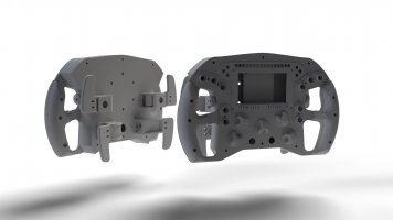
Here's what I have planned for it
  • 12 Momentary Push Buttons
  • 7 Rotary Encoders (5 at the front, 2 at the handles for the thumbs)
  • 2 Micro Switches for the Shifters
  • 2 Hall Sensors for the Clutchs (Double Clutch model)
  • 1 Potentiometer to be used as the Bite-Point selector on the Hall Sensors (not exactly sure it will work)
  • A Nextion 4.3" or a VoCore 4"
  • 22 WS2812B LED
That also looks like a handful for the board, would the USB be able to take care of all that energy-wise or should I think of adding an external power source?

I'm new to all this and tried searching around here, SimHub and Arduino forums before asking but couldn't really figure things out by myself, haha. My main concern is that warning, it got me confused if it would work or not. Also would appreciate some input on how to wire all that the best way possible.

Thanks!
 
Maybe have a look at the Leo Bodnar solution:


I used the one with connectors for a cockpit with buttons and encoders and for my DIY pedal set.
If you don´t want to wire the matrix LB has a brakeout board too which I used for my cockpit.

The one without connectors is still waiting for a DIY wheel project.

The size for this board is similar to a credit card.
Sounds small at first sight, but uses up a lot of space inside your fomula wheel.
But i can´t compare that to the size of an Arduino which I havn´t used till now.

( Offtopic: the simucube whireless board is roughly a quarter the size.)

MFG Carsten
 
Upvote 0
That one is quite interesting. And it seems that it doesn't need coding to make it work, right? Looking at their site I think it would be cheaper to buy the BBI-32 instead of the BU08364 + Breakout Board. That BBI-32 is basically a plug and play, easier to connect stuff. Shipping and price is a problem compared to Arduino though. Shipping to (and paying from) Brazil is a nightmare.

But it seems I can't use the LEDs or VoCore2 Screen on that one, right? I would still need and arduino for that?

Thanks for the help!

Edit - Just noticed there ain't no analog inputs for the BBI-32 :cry:
 
Last edited:
Upvote 0
If you want the input to be detected as and usb-hid you will need a board that supports this(Arduino pro micro/leonardo, Teensy boards...). With the amount of inputs you are planing to use, you will most likely have to do the programming yourself. To reduce the amount of pins to use on the controller board, you can for example put simple momentary push buttons and micro switches into a button matrix. Be aware that cabling will be a bit of a mess because the buttons are most likely not align like in a "standard" button matrix.
The rotary-encoders are a bit more tricky. In an ideal world, you will connect them to interrupt pins, which are limited on Arduino boards. In your case, the encoders alone will need 14 Pins. You can reduce this to one pin on the board by using an MCP23017. I do not know if simhub has support for this. So maybe you will have to do the programming yourself.
Both displays can't be powered using an Arduino. You will need to have a dedicated power source for them.

To be honest: maybe you should step down a bit from your original plan. Build a smaller, simpler rim or button-box with fewer buttons/encoders to get into it. Maybe learn a bit of Arduino programming beforehand. Solder some stuff, because this can be a big pain too. This way the frustration will be much less.
 
Upvote 0
  • Deleted member 1417362

In addition to this, if you want the clutches to work independently then you'll need two seperate analogue inputs, however they will be clutch x1 and clutch x2 not "Clutches" as such, so you'll have one paddle for a clutch and the other for say launch control.

However if you wanted to use the clutch paddles as two stage paddles with an adjustable bite point. So you set the bite point, release one paddle to launch then gradually come off the other as you pull away then you are best looking at the ascher racing board in addition.

This board allows you to add master and slave pots, and an adjuster pot - which then all connects to a leo bodnar board analogue input. And it only uses one input rather than x3.

 
Upvote 0
To be honest: maybe you should step down a bit from your original plan. Build a smaller, simpler rim or button-box with fewer buttons/encoders to get into it. Maybe learn a bit of Arduino programming beforehand. Solder some stuff, because this can be a big pain too. This way the frustration will be much less.
Yeah, I'm thinking about doing that. Just to understand everything before jumping into something that much complicated. Start with something easier will be better.

This board allows you to add master and slave pots, and an adjuster pot - which then all connects to a leo bodnar board analogue input. And it only uses one input rather than x3.
I saw that, but it's out of stock and ordering things to Brazil isn't really easy. I thought of using the hall sensors and the potentiometer on the clutchs after looking at the Ascher model, but in a more dyi way, haha.

Also, I found this project here Porscher LMP and thought of doing it with a Leonardo, a Micro and a USB HUB like that to put everything together. But I'll follow random_racer's advise and start smaller. Think I'll stick to testing the clutchs idea on a simpler GT model with a phone holder and keep using my cellphone on simhub for now.

Those Bodnar models seem to be the ideal thing to use on this bigger project, such as the LMP linked above, but they are pricey to me, and would probably risk having to pay for them again on customs.

I've added an image of what I'm planning, just to have some inputs on it. (Used bits of Formula B1 and Cosworth designs that are available on Thingiverse [Shifters, Handles and Buttons]).

Thanks everyone!
 

Attachments

  • Sem-título.jpg
    Sem-título.jpg
    90 KB · Views: 203
Upvote 0
  • Deleted member 1417362

Screen
either the vocor or nextion - i used nextion for my two - easy through simhub

Buttons
First of all i went arduino pro micro, then i went leo bodnar - i would just go straight to a leo bodnar now - its plug and play and you dont need to program it, depending on the board you get analogue and button input so you wont need a usb hub

Alternatively the STM32 is also a really good option, yes both are more expensive than arduino but you get what you pay for - and in this case its the time saving over programming.

clutches
Even simhub doesnt support the programming of analogue inputs for clutches because of the complexity, i also tried a leonado board and you will end up learning code, adapting code, testing and experimenting for days.


From what your saying, you will need a promicro for buttons, and leonardo for clutches\analogue\potentiometers, and you will also need a usb-ttl serial converter for the nextion unless you connect it via the promicro (which means you'll need to jumper the pin). So you will then need a x3 port USB nano hub - which will connect to a 4pin DIN connector, into a coiled USB extension lead

In my case - i had too much power loss after this and ran into undetected devices in windows.

Thats when i went leo bodnar board !
 
Upvote 0
clutches
Even simhub doesnt support the programming of analogue inputs for clutches because of the complexity, i also tried a leonado board and you will end up learning code, adapting code, testing and experimenting for days.
I was thinking of using the Accelerator axis for that. Having both hall sensors to the same pin, and one of them being damped by the potentiometer to regulate bite point.

In my case - i had too much power loss after this and ran into undetected devices in windows.
That's also something I'm afraid of happening, using a Micro, Leonardo with Leds and a VoCore through the hub seems like a bit too much for a single USB port. The project I posted earlier has a pin for additional 5v supply. But that's a specific HUB, as you can see here.


Maybe have a look at this project. Looks quite promising too.
The board itself is quite cheap, and the software has a lot of options.
That's a quite interesting one too. It seems to add everything I would need into that STM32. And that board is easier, and cheaper, to find around here. It actually goes for the same price of an Arduino Leonardo + Micro.

One problem with both STM32 and Bodnar boards is that I would still need an arduino to interface the Leds with SimHub, right?
 
Last edited:
Upvote 0
One problem with both STM32 and Bodnar boards is that I would still need an arduino to interface the Leds with SimHub, right?
Exactly. On the plus site, you can use one Arduino to control the LEDs and the nextion display. The only drawback is that you still need to think about the power distribution to the board(s) and the display and in the worst case of the LEDs too.
 
Upvote 0
Exactly. On the plus site, you can use one Arduino to control the LEDs and the nextion display. The only drawback is that you still need to think about the power distribution to the board(s) and the display and in the worst case of the LEDs too.
Got any advice on how to check for the power distribution/needs for a setup?

Anyway, I'll follow your previous advice and start from the bottom. I've already made a simpler model, only using the LED's and I'll try making the clutch for this one too, using only a Leonardo for now.
 
Upvote 0
Thanks! That article helped a lot. As per my calculations I would need at least 1A to power boards, leds and display. As to the USB HUB, I've been looking for that but can't really find one that has the option to add a second 5V input, do you know any? All I can find are simple hubs with only the PC USB (500mA) as power input.
 
Upvote 0
hi, I would like to share this software I have found recently.
It is really easy to use and you don't need to mess with arduino code.

The software made by “real robots”
https://www.youtube.com/channel/UCLXi-fkZu0hYgSBQV7Pagrw

you can have esp32 boards connected to Arduino pro micro in Serie and connect to PC via Bluetooth. Or 2 or more arduino pro micro connected in serie, and just one USB connected to the PC. That way, you can have more buttons then normal.
Recently he implemented Encoders. And you can easily create button matrix.

Video with ESP32 plus arduino:

First you need to upload this sketch to the eps32 or arduino:
https://gitlab.com/realrobots/rr_controller

Then, with this Software you can configure the controller, with a nice GUI.
https://gitlab.com/realrobots/rr_configurator

Easy and simple, and really cheap. Unfortunately not everything is perfect, the encoders aren't working perfectly. But for sure in the future he will improve.

Tiago Viana
 
Upvote 0

Latest News

How long have you been simracing

  • < 1 year

    Votes: 278 15.2%
  • < 2 years

    Votes: 188 10.3%
  • < 3 years

    Votes: 190 10.4%
  • < 4 years

    Votes: 139 7.6%
  • < 5 years

    Votes: 248 13.5%
  • < 10 years

    Votes: 219 11.9%
  • < 15 years

    Votes: 134 7.3%
  • < 20 years

    Votes: 112 6.1%
  • < 25 years

    Votes: 84 4.6%
  • Ok, I am a dinosaur

    Votes: 241 13.1%
Back
Top