G27/G29 Hall Sensor Mod

Thought it might be an idea to share some ideas @Neilski and I have been bouncing around about replacing the stock pots in the G27 and G29 with Hall Sensors (probably also work on a G25). We found a few discontinued options (e.g. https://www.simulaje.com/productos/accesorios/sensor-hall.html) and a current one that seemed ok but required a USB adapter (https://tomyracing.com/index.php?language=en&module=products&content=pedhallv130), which made us suspect its range might not be great and/or it didn't invert the signal. (EDIT: I didn't read the description properly! the mod can be used without a USB adapter)

So, in the interests of science we decided to get some bits and have a play. We went for the A1324/5/6 (https://docs.rs-online.com/958c/0900766b813d193a.pdf) as it appeared to have decent range of close to 0-Vcc (many are just +/-1v) and @Neilski worked out a simple arrangement that theoretically would produce a near linear change based on angle over the 70 deg the G2X rotates the pot:

1600181340738.png


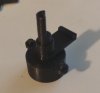
This was then a great excuse to get a 3D printer, so I ordered an Ender 3 Pro (https://www.creality3dofficial.com/products/creality-ender-3-pro-3d-printer) and knocked up a simple model to hold the magnet and sensor whilst still utilising the existing pot for simplicity. The result was the following:

g2x_mag1.jpg


IMG_20200913_155039.jpg

Assembled and connected up to an Arduino to measure against the pot
IMG_20200913_164101_2.jpg


It's got an interference fit that seems fine and allows adjustment of the sensor angle to get the range as centred on Vcc/2 as possible. We played with some different magnet sizes, but found the 8mm with the most sensitive device (A1324) gave a range just over that of the stock pot. BLUE line is the pot, RED is the hall sensor

hall-v-pot-8mm.png

We are still playing but this is looking really promising as a simple swap for the standard pots in the G27 and everything but brake in a G29, although a less sensitive device like the A1326 could probably get the range down to that expected (more testing required!)

EDIT: forgot the link to the 8mm model - https://a360.co/3mvHXkX
 
Last edited:
Not sure if the charts I posted above are very clear, but they show that the pots inside the G29 are as linear as the A1324 and I suspect those in the G27 are the same after @Neilski and I compared part numbers. They have a reduced range of rotation to an off-the-shelf 10K though, which I think is the actual problem.
Agreed. The Logitech pots all appear to be entirely linear, and have a roughly 70° angular range, as opposed to "normal" pots which are indeed more like 300°.

Those pots look very cool @DaVeX↯!
 
Upvote 0
Got around to making the pots based on @DaVeX↯ 's design

hall_pot_pieces.jpg

hall_pot_assembled.jpg

hall_pot_installled.jpg

It's actually slightly smaller than the stock pot. I have a few tweaks in mind to make it a bit more robust, but it seems to work ok. It's not exactly the smoothest motion, but it doesn't seem noticeable when pressing on the pedal
 

Attachments

  • hall_pot_assembled.jpg
    hall_pot_assembled.jpg
    36.2 KB · Views: 97
Upvote 0
Got around to making the pots based on @DaVeX↯ 's design

View attachment 422163
View attachment 422164
View attachment 422165
It's actually slightly smaller than the stock pot. I have a few tweaks in mind to make it a bit more robust, but it seems to work ok. It's not exactly the smoothest motion, but it doesn't seem noticeable when pressing on the pedal

I bet if you used damping grease like Nyogel 767a in the pot it would move/feel as if it had sealed bearings. It's expensive grease just to check for funsies but I have some on hand (I use it for precision friction mechanisms for joysticks/throttles etc) and can send you a tiny bit in a small ziploc in an envelope if you want to try it out. It's not like greases from the hardware store.. it's related to the stuff that makes telescope/microscope/camera parts move with super smooth resistance. If your interested, pm me and I'll send you a sample
 
Upvote 0
Got around to making the pots based on @DaVeX↯ 's design

View attachment 422163
View attachment 422164
View attachment 422165
It's actually slightly smaller than the stock pot. I have a few tweaks in mind to make it a bit more robust, but it seems to work ok. It's not exactly the smoothest motion, but it doesn't seem noticeable when pressing on the pedal

Love it and how you improved it!!!
Seems sharing ideas brings always to good things!
And yes I forgot, you need to put some grease/silicone the best and cheap one I used was the Tamiya one (the one they use for Mini4WD models).

Really happy to see it evolving, curious to know how the lock works and how you seal it, I gave it a cubic form since I was thinking to put some small screws (glasses ones) on the cover angles...
 
Last edited:
Upvote 0
Did you consider making the clip (the last piece on the right in the pic) a little bit higher and flip the top part?
This way when you insert it the top part will touch the metal and should help keeping in place the pot when subject to rotations...(Sorry I am not ENG native so I try to explain the best I can)
Yeah, I actually made it high enough so you can put it in with the tab flush to the top of the metal base. The exploded diagram is just showing it in the orientation for printing. It's not necessary to stop the rotation though as the front face has two small dowels that locate into two alignment holes above and below the shaft hole.

Adding the grease helps smooth the motion and also reduce the free play a little. There is a still a slight flexing of the model at the start of rotation due to the pre-load of the spring, but removing the spring causes noticeable hysteresis

I'm not entirely sure about the durability of this with PLA, but it's incredibly cheap and quick to make. Takes about an hour to print all the parts and costs about €0.10 in materials
 
Upvote 0
Yeah, I actually made it high enough so you can put it in with the tab flush to the top of the metal base. The exploded diagram is just showing it in the orientation for printing. It's not necessary to stop the rotation though as the front face has two small dowels that locate into two alignment holes above and below the shaft hole.

Adding the grease helps smooth the motion and also reduce the free play a little. There is a still a slight flexing of the model at the start of rotation due to the pre-load of the spring, but removing the spring causes noticeable hysteresis

I'm not entirely sure about the durability of this with PLA, but it's incredibly cheap and quick to make. Takes about an hour to print all the parts and costs about €0.10 in materials
Thanks for reply and for your time!
Sounds perfect!
About the shaft I remember I had an issue with it related to flexibility (and eventually breaking it),I solved this putting a long thin screw inside of it (I did the hole first with a small tool).
Probably PLA is ok but I think an harder material is needed for improved durability.
 
Last edited:
Upvote 0
I had an issue with it related to flexibility (and eventually breaking it)
I don't understand how that could be possible - on my G27 pedals, I could have sworn that the metalwork of the pedal arm itself limits the travel at both ends, which should mean that the spring is the only thing producing any torsion on the shaft, and even that should only be when the pedal is completely released, because the gears disengage when the little plastic arm hits the base. (Or perhaps my memory of how it works is faulty?)
 
Upvote 0
you are correct but G27 pots are sturdier than 3D printed ones (specially if you are using PLA and printing isn't optimal).
The 3D printed shaft needs to be very well printed and betters if you use a sturdier material than PLA mainly due the print process (the shaft will be printed as a series of "small circles" from the bottom to the top).
 
Upvote 0
Adding the silicone grease helps to smooth the motion considerably, but I'm still not sure on the durability of the materials due to the forces exerted on the model by the retaining spring. I'm going to install it my accelerator pedal and after a few months I'll pull it out to see how it held up
 
Upvote 0
hello guys, I read the thread with great interest, I use the pedal board of the G27 and for some time I wanted to replace its potentiometers. unfortunately my knowledge in electronics is really limited, but I can be a tester if it can be useful, I can manage with soldering , CAD and 3d printing. Is the working design currently that of GitHub? Sorry for my bad English.
 
Upvote 0

Latest News

Are you buying car setups?

  • Yes

  • No


Results are only viewable after voting.
Back
Top