Foldable aluminium rig suggestions?

Hi all.

I currently use a desk with a G27 clamped on to it. It's important to me that it's not fixed so I can use the PC for other things. For those that don't know, "other things" is a general term for tasks that do not involve sim racing ;)

I sometimes toy with the idea of getting a new wheel, possibly even direct drive, and I know that a simple desk won't cut it. Aluminium profile seems like a good sturdy mounting solution but most of the things I see out there are fixed.

Here's my current arrangement with the wheel/pedals not in use:
1. Normal Desktop.JPG
Note the keyboard tray clamped on to the desk.

Here's the most common use with the wheel:
2. Steering Wheel in Place.JPG
  • I don't have the skill to use the gear lever/clutch properly so the former is just clamped on to allow me to use the buttons for a few things.
  • The pedals are screwed to a piece of my old desk which has a hole cut out to stop them/the chair sliding away from each other.
  • There's enough room to slide the keyboard tray out, which is nice but not essential.
If I do decide the try the gear lever, another part of my old desk can be clamped under the wheel with a tab sticking out on which to clamp the lever:
3. Gear Lever Mount 1.JPG5. Gear Lever Mount 3.JPG4. Gear Lever Mount 2.JPG
That board was rectangular but I cut out a piece to make it an L shape, which allows the gear lever to be closer. The wooden blocks are glued on and act as spacers to lower the board.

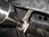
Gear lever attached:
6. Gear Lever Setup.JPG

Generally the setup works but it's a bit cumbersome to arrange. The hole in the pedal board was initially cut to allow the chair casters to fit perfectly in the middle (when I was always using the clutch). I later made a rather crude alteration when I went back to just using the throttle and brake and the casters were replaced with stands.

Given what you've seen above, can anyone suggest a design for an aluminium profile rig that would fit around that desk and be sturdy (with DD or may just a belt driven wheel) yet foldable so I can put it away? The space on the left of my chair is fine to use.

This shows an example of hinges for swivel arms:
Would they be sturdy enough to use or might there be too much flex?

Also, I'd be willing to replace the desk completely it that gets in the way of a good solution.

Here's a rather crude diagram of how the wheel might fold away (rests on the desk but held in place at the front with aluminium profile and can rotate forwards/downwards for storage)
7. Hinge Suggestion.jpg
 
Last edited:
Thanks, but the aim of the new rig is to support a direct drive wheel. I've also considered cutting out a part of my desk to allow more choice of wheel position, but I'm not sure if it would weaken it or if I could slot it back in for normal use.
 
Upvote 0
Thanks, but the aim of the new rig is to support a direct drive wheel. I've also considered cutting out a part of my desk to allow more choice of wheel position, but I'm not sure if it would weaken it or if I could slot it back in for normal use.
Though it doesn't include your foldable requirement, this looks like a sturdy base to start from
 
Upvote 0
Hello again. I've not done much driving since the beginning of the year so this idea went on the back burner. But it didn't go in to waste disposal!

I'm not so sure of the wisdom of making the rig foldable because I don't think hinges were made with force feedback motors in mind.

Revised idea:
1609027504649.png


The lighter coloured frame at the bottom is for the pedals (details of angles to be decided) and it can slide back and forth. The vertical portion is now fixed (as shown by the crudely drawn connectors).

These links have been posted before in this thread but just to keep things together, the above is a combination of the compact front of this design:
1) https://www.racedepartment.com/threads/show-us-your-rig-cockpit.19/page-203#post-3192952
(no seat mounting, in my case just dropping the two front feed over a bar)

with the sliding pedal box of this design:
2) https://www.racedepartment.com/threads/new-80-20-rig-design.164984/

My main concern is that the beam at the back of the desk will prevent the pedals going back far enough, but I might be able to get away with it if I copy the angled pedal mount in link 1. The wheel in the design is tilted back but it can be straightened. The vertical beams provide some leeway with the height, but what I'm finding hard is to visualize how I'd be sitting.
My G27 gets clamped to the desk so it's not too high, but it has a backwards tilt which currently requires me to raise my chair. The above design has the pedals higher than I've been using, so I might want them further back for the ergonomics. I'm not too bothered about a realistic racing car position.

The short version is: generally speaking what strategies do people recommend to allow for a design not tuning out as expected. E.g. extra brackets/bolts etc, and maybe an extra length or two of profile some more height adjustments etc?
 
Last edited:
Upvote 0
what strategies do people recommend to allow for a design not tuning out as expected
That is the classic research and development issue. From math, one can generalize that the form of a question largely dictates results, within constants determined by boundary conditions.
For this problem, my experience has been that a sim steering wheel at or above desktop is actually above ideal height at a less than ideal angle. Specifically, given a swivel desk chair, a wheel stand beside the desk works for me, using VR and a cheap ratchet strap with hooks to locate the chair relative to pedals when driving.
 
Upvote 0
a sim steering wheel at or above desktop is actually above ideal height at a less than ideal angle.
Unless there's a practical reason I think that's subjective. It's also relative. If the pedals and monitor are also high then surely it's not a problem.

Anyway, there are storage problems with my idea of moving the rig out from the desk, so I've had another idea: Make a fixed rig (still using the compact design based the first of the two compact designs, but have the desk raised above (using some kind of crank) which can be lowered for desk use. The monitor/spakers could be secured to the rig with a swivel arm to allow them to be positioned correctly for either scenario.

Animation:
 
Upvote 0
Bump!

I've modified the idea again. Sliding the desk up and down looks good in an animation but I wasn't having much success finding lifting mechanisms that wouldn't cause further issues (like swallowing a fly, followed by a spider etc).

Here's the latest idea, where the desk slides back and forth. Still to be worked out is a way of allowing the monitor to move. Is it overly ambitions to want something that can be converted from a rigid sim rig, suitable for direct drive, and a sit-stand desk?

 
Upvote 0
There are chinese-made electric scissor jacks that would work well in your situation. One of those would allow you to skip the step of attaching a handle and worrying about adequate clearance of the handle.

I think skipping the hinges is a better idea. The mass is not going to be stable when stored up against the wall unless you lay it on its side or have straps to hold it in place.
 
Upvote 0
I've had a rethink, which may or not be a good thing - you be the judge!

Base/wheel setup:
1612217300325.png

Pedal deck not designed yet, but that should be fairly conventional. Not yet sure about attaching the seat. It may just hook over the front of the base. The main focus here is in supporting the DD wheel motor. It's much further back than in normal rigs. In red is a quick release, connected to an extension shaft, with a bearing (orange) to support it and take horizontal and vertical stress off the motor. Not sure if this is possible to design, or if the components exist.

Desk in place:
1612217577121.png

I'm only drawing the top; it does have side/back pieces. Part of the top would be cut out to allow space for the rig/motor, but otherwise it's the same as my current desk. The bearing would somehow rest on the desk. Not sure how, as it's not a standard set of components.

Monitor speaker on sliding stand:
Front:
1612217913632.png


Back:
1612217979972.png


The blue pieces are supports for linear sliders. Notice how the front has two rollers to support the weight when the monitor is in the forwards position. I'd prefer to have the sliders inside the uprights supporting the wheel, but I may not have enough clearance for their support brackets.
The speakers are on some sort of plate, but I'm not sure about how that would work - I'd prefer to avoid drilling holes, so some short profile sections with plain panels may be better.

When not driving I can slide the monitor/speaker assembly back:
1612218349987.png

I'm aware of the need to limit the sliding range so it doesn't fly off.

Detach the wheel:
1612218493089.png


And I have a PC desk!
I could make some sort of cover to hide the wheel motor, but that would just be a cosmetic thing.

It may be necessary to do something with the pedals - maybe they could fold upwards when not in use.

Pros: If this works it'll solve the problems of the previous designs as this doesn't have to be moved. Nor does the desk have to move. The only storage required is for the wheel.

Cons: the extended steering column, support bearing and a matching quick release mechanism might not exist.


I'd love to read peoples' thoughts or suggestions about the above (especially the things mentioned in the 'cons' section. For supporting the extended column, would wood work work?
 
Last edited:
Upvote 0
For years hot rodders have repurposed old con rods as steering column supports. You could invert the rod from the orientation in the photo and mount it to a wide block.

I have a beautiful billet aluminum piston connecting rod from a 500 cubic inch Top Alcohol funny car which I purchased for USD $10.00. After a few 1/4-mile passes these marvels of engineering art are just paperweights which alcohol and nitro teams gladly sell as souvenirs.
 

Attachments

  • IMG_1904a.JPG
    IMG_1904a.JPG
    74.4 KB · Views: 82
Upvote 0
Your last idea is quite innovativ :cool:
Havn´t seen or heard of such thing.

The part with the quick release and the spacers is not to difficult, these things can be bought ready made.

Just as an example:
https://external-content.duckduckgo...id=OIP.BX4YoLVlkDnz_mvBGs37zwHaHa&pid=Api&f=1.

I probably would not combine two of them because of the leverage and you should use a solid quickrelease without play!!
The SC2 should be fine, thats rock solid.
BTW, the stock SC2 quick release with the stock spacer is already 115mm long to the steering wheel mount, the wheel I´m using is another 70 from mounting plane to front plate.

And since the SC2 ´s motor is quite low profile with it´s height of 130mm it possibly could just sit under the monitor.

MFG Carsten
 
Upvote 0
Tonight in bed ( don´t ask :cool:)
I had another idea which was develeoped further after whatching you excellent video.

How about an all-in-on solution?


Bolt a profile frame to the wall, mount the the pedal tray and chair holder to it, solid or with sliders to get legroom while working,

bolt a desktop frame to it, probably with sliders to gain workspace,

bolt the wheeldeck to it ( to slide or rotate out when needed)

bolt a pivoting monitor mount to it. ( these should be available ready made and cheaper than DIY, depending on the wheight of the monitor)

use any mounting method to fix your speakers to the back frame.

With the sliders shown in your video you should be able to acchieve enough clearance for your steering wheel when sliding the desktop in and the wheeldeck out.

The monitor would just swivel out of the way for that operation.

Only concerm would be tne stiffness of the wheel deck because it would be farther from the frame than in normal rigs. That should be overcome by the use of 80/120 or triangulation.

Overall there should not be much movement in the wall mounted simrig except for earthquakes :mad:.

In case the idea is not clear could whip up a sketch.
( Pencil and paper, I hate computers)

MFG Carsten

Another (after) thought:

when you use your future DD wheelwith the appropiate FFB and acompany it with loadcell pedals
you will HAVE TO keep your chair from moving AT ALL, especially swiveling.

So better devise a way to bolt your chair to the rig with a quick release.
 
Last edited:
Upvote 0
Some commendable enthusiasm in the last few replies.
I don't want to seem like I'm shooting things down, but my desire is already unconventional enough so I'd like to stick to things within my limited understanding and experience.

A conrod to support the shaft - a nice idea but I'm not sure how I'd mount it or if I could find one with the correct dimensions.

The idea of bolting the frame to the wall etc seems too complicated. That's outside my experience, so I wouldn't trust myself to get it level or not bodge it in some other irreversible way.

Having looked the the Simucube parts a bit more I see now that the red quick release in my design won't be needed as the motor already has a QR.

My current 3d model is based on the dimensions here:
https://cdn.shopify.com/s/files/1/0...ucube_2_pro_dimensions_1296x.JPG?v=1603312365

It says the shaft is 66.5mm long, with an 8mm collar. My 3d model doesn't use the collar. No pun intended but it has no bearing on my design as I don't need that level of detail. Instead my 3d model has the shaft as 74.5mm, as if the collar was flat.

With the stock spacer, does that add 70mm on to the front face of the qr mechanism, like this?

1612482486514.png1612482628468.png

For the shaft, I really like the look of this design:
https://community.granitedevices.com/t/simucube-2-sqr-extension/2463/26

For a support bearing these look like good things:

The spherical part compensates for misalignments of of the shaft which sounds like something that I'd end up with.
They support shafts up to 50mm diameter. Does it look like the shaft in that granitedevices link is 50mm?

There's a lot of terminology I'm not familiar with, and what certain things are called and what sizes are standard etc. This is an area I need advice in.

E.g the final part of the mounting system:
From what I've read the outer holes have a PCD of 70mm (I had to look up PCD).
I've also edumacted myself about the bolt numbers, e.g. m5x0.8
It that a standard pattern? If so it should make it easier to build the shaft assembly.

But what would I look for? E.g. a 50mm diameter shaft of the desired length with flanges matching the above bolt pattern at either end? How would it be assembled? Would the flanges have some sort of clamping system so it can be put together without welding?

In short I think I know what I want but I'm not sure what to search for, and what things are standard.
 
Last edited:
Upvote 0

In this thread you found anything you need:

the SC2 motor shaft is 22mm.
You can buy ready made adapters 22mm to PCD 70 you could use like this:


mount the motor side SC2 quick release to the motor,

bolt one 22mm/PCD adapter to the wheelside quick release ( with a "star adapter like in your last link)

shove a 22mm shaft/pipe into the adapter

mount your steering wheel onto the shaft with another 22mm/PCD 70 adapter.

And your done ;)

I´m not even shure you would nead a bearing on the shaft, but the guys from Granite devices could answer that.

The included SC2 QR and two 22mm/PCD70 adapters plus shaft would be everything needed.

( personal opinion i can´t hold bach, feel free to ignore :rolleyes::

I myself would rather move the whole motor with sliders than build something this unusal.
I ´d have a better gut feeling with a shorter shaft.)

Good luck and success Carsten
 
Upvote 0

Latest News

How long have you been simracing

  • < 1 year

    Votes: 325 15.5%
  • < 2 years

    Votes: 224 10.7%
  • < 3 years

    Votes: 217 10.3%
  • < 4 years

    Votes: 166 7.9%
  • < 5 years

    Votes: 281 13.4%
  • < 10 years

    Votes: 242 11.5%
  • < 15 years

    Votes: 158 7.5%
  • < 20 years

    Votes: 121 5.8%
  • < 25 years

    Votes: 93 4.4%
  • Ok, I am a dinosaur

    Votes: 273 13.0%
Back
Top