Hi,
ATM I’m returning slowly to Sim Racing again and I’m mostly racing with ACC. So I decided it was time to have one more steering wheel. A GT3 style, since I only have the Fanatec BMW GT2. And I decided to make my own, since I love to design parts and I have a 3d Printer.
Background:
For the hub, I was going in the direction of the Sim Racing Machines Emulator Hub, but the final price was almost the same as the Fanatec Podium Hub (probably 30€ dif). So I decided to go with the official hardware.
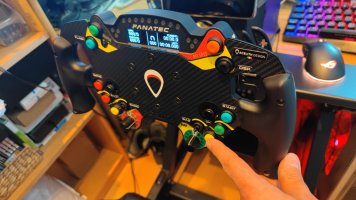
For the Steering wheel, I was thinking about buying one from 3drap.it. But, at the last minute I saw for sale a brand new Thrustmaster Open Wheel (TOW) steering wheel rim with a really good price. (Someone bought a TOW and replaced the rim with one from https://acelith.com/. So, I was lucky to get it brand new!!!)
The Idea:
Since the Podium Hub doesn't come with buttons, just the connectors for the buttons, I had to make some investigation on how to connect my wheel buttons on the hub. Unfortunately I didn’t find all the answers on the internet, so I had to make some investigations, and now I will share all the secrets of the Hub here. (Later in the post you will find them, be patient).
But the Fanatec Hub only accepts 10 buttons and 2 potentiometers, and for me that isn’t enough, I will have in parallel an ESP32 board to have more buttons and rotary encoders.
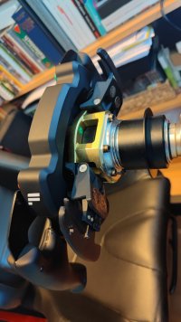
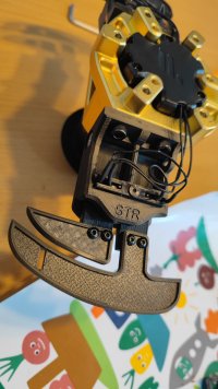
The advantage of using the TOW is the quality. Already painted and the handles are really well made (sorry 3drap and acelith, but yours aren’t that impressive). But unfortunately not everything is perfect. The hole pattern from the Podium hub is 6xØ70mm M5 or 3xØ50mm M5. And the hole pattern of the TOW is 6xØ58mm M4. So, I had to make an adapter plate, but unfortunately I didn’t find, so far, a good solution for using all the fixing holes from the hub and the TOW rim. This is a problem I will try to solve later on.
The 3D model of the wheel:
Free to use and modify at Onshape:
 cad.onshape.com


Electronics:
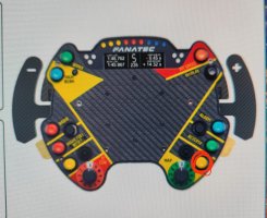
The goal is to have 4 Rotary Encoders and around 12 press buttons. Since the Podium Hub is limited with the quantity of inputs, I will connect all the Encoders and some extra buttons on the ESP32 board.
This will give me a lot of flexibility. Because when the wheel is connected, even if the board stops working, for some reason, I will have the buttons attached to the hub working (ex. Paddle Shifters).
The ESP32 board will be connected to the PC with bluetooth, and it will be powered by the USB C port on the bottom of the hub. So, I will not have any cable coming out of the wheel.
ESP32 sketches:
I’m using the software made by “real robots”
https://www.youtube.com/channel/UCLXi-fkZu0hYgSBQV7Pagrw
Sketch (arduino and esp32):
https://gitlab.com/realrobots/rr_controller
Software to configure the controller
https://gitlab.com/realrobots/rr_configurator
For more info, check his youtube channel and his tutorials. The way it works is easy and you don’t need to know how to write arduino code.
Finally the Podium Hub schematic:

All the power output in the electronic board is 3.3V. The USB C power output is 5.0V
All the JST connectors needs to be trimmed the hooks on both sides, like in this pic:

USB C power will be taken with this USB C pcb board:
...coming soon...
finally. In my google photos shared folder I will add pic of the wheel.

Tiago Viana
ATM I’m returning slowly to Sim Racing again and I’m mostly racing with ACC. So I decided it was time to have one more steering wheel. A GT3 style, since I only have the Fanatec BMW GT2. And I decided to make my own, since I love to design parts and I have a 3d Printer.
Background:
For the hub, I was going in the direction of the Sim Racing Machines Emulator Hub, but the final price was almost the same as the Fanatec Podium Hub (probably 30€ dif). So I decided to go with the official hardware.
For the Steering wheel, I was thinking about buying one from 3drap.it. But, at the last minute I saw for sale a brand new Thrustmaster Open Wheel (TOW) steering wheel rim with a really good price. (Someone bought a TOW and replaced the rim with one from https://acelith.com/. So, I was lucky to get it brand new!!!)
The Idea:
Since the Podium Hub doesn't come with buttons, just the connectors for the buttons, I had to make some investigation on how to connect my wheel buttons on the hub. Unfortunately I didn’t find all the answers on the internet, so I had to make some investigations, and now I will share all the secrets of the Hub here. (Later in the post you will find them, be patient).
But the Fanatec Hub only accepts 10 buttons and 2 potentiometers, and for me that isn’t enough, I will have in parallel an ESP32 board to have more buttons and rotary encoders.
The advantage of using the TOW is the quality. Already painted and the handles are really well made (sorry 3drap and acelith, but yours aren’t that impressive). But unfortunately not everything is perfect. The hole pattern from the Podium hub is 6xØ70mm M5 or 3xØ50mm M5. And the hole pattern of the TOW is 6xØ58mm M4. So, I had to make an adapter plate, but unfortunately I didn’t find, so far, a good solution for using all the fixing holes from the hub and the TOW rim. This is a problem I will try to solve later on.
The 3D model of the wheel:
Free to use and modify at Onshape:
Onshape
Sign in to Onshape, the #1 fastest growing CAD system in the world with over 4 million users.
cad.onshape.com
Electronics:
The goal is to have 4 Rotary Encoders and around 12 press buttons. Since the Podium Hub is limited with the quantity of inputs, I will connect all the Encoders and some extra buttons on the ESP32 board.
This will give me a lot of flexibility. Because when the wheel is connected, even if the board stops working, for some reason, I will have the buttons attached to the hub working (ex. Paddle Shifters).
The ESP32 board will be connected to the PC with bluetooth, and it will be powered by the USB C port on the bottom of the hub. So, I will not have any cable coming out of the wheel.
ESP32 sketches:
I’m using the software made by “real robots”
https://www.youtube.com/channel/UCLXi-fkZu0hYgSBQV7Pagrw
Sketch (arduino and esp32):
https://gitlab.com/realrobots/rr_controller
Software to configure the controller
https://gitlab.com/realrobots/rr_configurator
For more info, check his youtube channel and his tutorials. The way it works is easy and you don’t need to know how to write arduino code.
Finally the Podium Hub schematic:
All the power output in the electronic board is 3.3V. The USB C power output is 5.0V
All the JST connectors needs to be trimmed the hooks on both sides, like in this pic:
USB C power will be taken with this USB C pcb board:
...coming soon...
finally. In my google photos shared folder I will add pic of the wheel.

Tiago Viana
Last edited:
")