Arduino Leonardo wheel.

yeah, maybe reaction time little bit worse in scooter motor. but i allraedy tryed bs simulator wheel and i think it feels nicer (my opinion), and feels more torque in the hand...
(i try bs simulator wheel when he still using 1.5:4 ratio)
 
Upvote 0
some chart update...
max gain 49% @900degree
49%.jpg


max gain 54% @900degree
54%.jpg
 
Last edited:
Upvote 0
ahoenksiluman
Have got an idea. Make the physical stop to wheel rotation in 900 degree range lock to lock. Or what ever. Concerning this motors and heavy wheels. At least just for the test. )

And put 600 ms step in wheel check.

And the secret to that cool range with Beano Servo chart comparison to other wheels. And that dude, duped it with his results near by.
600ms instead of 300ms in wheelcheck. And you've got the full range of the wheel rotation in a test. AS if it so cool.. I busted it. He putted 600 ms, but give away it as if for with 300 ms signal charts. And he fooled on purpose. There is no almost so much difference with his wheel or any other. As was presented.
 
Last edited:
Upvote 0
Make some sort of rotation rate check on video analysis to MY1025 motor.


12V/12.5A instead of 24V14A nominal power. Also half of the power from wheel check too. i.m. 50%Saturation X 1/4 gear ration. With 50satx/ it means 50% of power in wheel check.

900 deg /360 = 2,5 lock to lock range
900 deg for 700ms - lock to lock 700 ms lock to lock / 2.5 rev = 280 ms 360 degree. 1 wheel revolution.
1000 ms / 280 ms = 3.57 rev/sec 210 rev.minute rotation rate.
 
Last edited:
Upvote 0
Got an idea.

To use 100ms or 150 ms instead of 300ms default in wheel check, to see the chart as is with 900degree. Or may be even less?
I guess for powerful MY1016/1025 etc motors,the 300ms default signal is too much for them, and with small gear ratios, "to read" the charts as they are supposed to be read. Simply put, they just ran away with easy and fast beyond the reading limits with 300ms. And less amounts should be taken. The charts of ahoenksiluman are good examples.
Thus, there are may be no such a big wrong issues as big inertia of the scooters and alike. They just fast and powerful for the "300 ms readings".
 
Last edited:
Upvote 0
According to the made on step test data.
MY1025 -12V(half voltage) No wheel attached, Chain drive , 1:4 gear ratio
6ms to respond from start of the signal to rotate.
Start to 360deg for 101ms
1000ms/101ms = 9.9rev/sec = 594rev/min
Takes 109ms to 450deg (Make with ease, 1350 deg. with default 300ms wheelcheck signal duration, that is too much with default chart and test analysis)
 
Upvote 0
The correction after video was wrong. The initial calculaltions on step test data logs were correct.
So the charts in numbers. One rev to 360deg from 0 revs, and time for it. Responce time from the moment the signal are made.

Some DIYs and not only for comparison.

Motor770, (100% gain, basicaly 50% gain are used)
(362.84deg-0.13deg) ( i.m. how many degree close to 360deg, were taken for calculations, and time to reach it consumed.)
362.71deg for 184ms
1000ms/184ms = 5.4rev/sec = 324 rev/min minimum.
8ms to respond from start


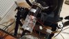
My1025, without wheel, with 12V, 12,5A (150W instead of 300W the motor requires) 1:4gear
(368.53deg-8.76deg)
359.77deg for 208ms
1000ms/208ms=4.8rev/sec = 288rev/min minimum.
12ms to respond from start


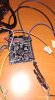
BSSim My1016, 1:4gear (50% GAIN Mmos)
(366.59deg-1.79deg)
364.76deg for 236ms
1000ms/236ms=4.2rev/sec = 252rev/min minimum.
6ms to respond from start


POWER steering motor, Conventional steering wheel, 18.8V
(362,32-0,26)
362deg for 236ms
1000ms/236ms = 4.2rev/sec = 252rev/min
4ms to respond from start


CGWheel (Caravangoes), Lightweight wheel, 1:3 gear.
360.94deg for 246ms
1000ms for 246ms=4.06rev/sec = 243.6 rev/min minimum.
8ms to respond from start

And.

OSW Direct Drive, Sparco
(361.47-0.39)
361deg for 304ms =3.28rev/sec=198rev/min
2_ms to respond from start


G27
Just a chart)
10ms respond from start.


The scooter motors for ffb wheels, are quite a "that’ll do".
grin.png


IR ffb gain was 12% enough. Without IR LUT add on.

Once again the my1025 rotaion rate. Ordinary heavy wheel.

Also the BSSim vids.
https://youtu.be/yiHT_YgN8Aw

Only, are there a need to use 24V12.5A for 300W motor, (if now 150W-12V,12.5A, are used with 300W motor) if the Mmos (whatever), BSSim gain is set to 50% with full power supply? Guess that'll be all the same. Or better use full power, as the motor requires, and then just set the gain in software?
 
Upvote 0
wheel works fine :)
MMos, STM32, 4xBTS, 5x Fan :-D 50A


Attachments

  • 54409207_399443600893197_3339448625825579008_o.jpg
    54409207_399443600893197_3339448625825579008_o.jpg
    120.3 KB · Views: 707
  • 53852504_396432667860957_1053805041078501376_n.jpg
    53852504_396432667860957_1053805041078501376_n.jpg
    65.4 KB · Views: 1,003
Upvote 0
Jan Pokorny, Excellent work! Congratulations, you make it work!
And as usual:geek::D - Step test log please :);) Very interesting.
____________
Emanuele Succurro DC DD linearity test.
My1020 500w, 15v 50a, n2 bts7960, encoder omron 1000 ppr, stm32f4 mmos.

_______________

Another DD DC.
maddex
https://photos.google.com/share/AF1...?key=VTdxbzNlZHRZdmxhbUFWQVJXdHNYaWFSOHN0VVB3


DC DD wheel.(motor for floor cleaners (laborwash) 0,75 kw 48vcc 4 brushes, )
66A / 12.1V
362deg за - 230ms
4.34rev/sec = 260rev/min minimum
 
Upvote 0
Decided to give a go with DIY H-bridge for the arduino DIY wheel, as an alternative replacement for BTS drivers.
Just curious.

The test with 5v to controll inputs, to change the directions.
And 12V power supply.

The schematic was taken from here.
https://www.circuitlab.com/editor/#?id=m4c244

Made with Manhattan components mounting style.
The MOSFETS are: for P-channel IRF4905, and N-channel - IRF3205.
As there were no slugs to isolate the mosfets from the radiator, made quickly and simply with thermal contraction tube and plumbing flax fiber.


Question how that should be better connected with controller. Gues only with PWM left/right.
Or should that be like with inverter PWM+Dir mode like here.

Also should be tested with some PWM signals. )

Please write your suggestions, on enhancements etc.
 
Upvote 0
The schematic was taken from here.
https://www.circuitlab.com/editor/#?id=m4c244

Made with Manhattan components mounting style.
The MOSFETS are: for P-channel IRF4905, and N-channel - IRF3205.
As there were no slugs to isolate the mosfets from the radiator, made quickly and simply with thermal contraction tube and plumbing flax fiber.


.
Wow, big thumbs up for trying alternative driver solution. I had similar board in mind (althougth with IRFZ44 on low side and fast optocouplers driving gates), and even designed board layout but was too lazy to build and test it.
I guess for your schematic gate current for low-side MOSFET's can be a bit of a problem for Arduino, suggesting limiting resistor.
 
Upvote 0

Latest News

How long have you been simracing

  • < 1 year

    Votes: 352 15.6%
  • < 2 years

    Votes: 247 10.9%
  • < 3 years

    Votes: 243 10.7%
  • < 4 years

    Votes: 177 7.8%
  • < 5 years

    Votes: 301 13.3%
  • < 10 years

    Votes: 259 11.5%
  • < 15 years

    Votes: 166 7.3%
  • < 20 years

    Votes: 126 5.6%
  • < 25 years

    Votes: 99 4.4%
  • Ok, I am a dinosaur

    Votes: 291 12.9%
Back
Top