Yeah i read already that i should only use dds. I just used png for testing purposes and somethimes it didn't even work.
Regarding the Satellite image. Why is the diffuse so dominant that i can barely see the detail maps? Is there a way to tone down the opacity of the diffuse (satellite image) so i can see more of the detail textures? It's currently absorbing the colors of the detail maps. Thanks
A general rule of thumb is If you have color in the diffuse then the details should be in greyscale. If you have color in your details then the diffuse should be greyscale. I prefer color in the diffuse if possible.
Does anyone know how to utilise delaunay triangulation of a mesh in 3ds max?
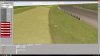
I'm trying to get my track's physics mesh as close to Kunos' as I can, and theirs seem to be subdivided into roughly equilateral triangles (looking at Nords). I am able to achieve this in theory if I start with a plane and then use delaunay subdivision (bottom object in screenshot), but if I start with a section of my road's mesh it doesn't work the same way (top object).
My road is created from a lofted object, then converted to a mesh. For my test I then converted to patch, then Nurbs, then set subdivision to delaunay, but I don't get the neat triangles I see when I start with a plane
I would love to know how Kunos create theirs so I can try to replicate the same feeling in my track. Can anyone help?
The bottom one looks like the modifier "Garment Maker" (available only to a closed spline)
meaning you wouldn't keep the middle elevation of your road, you would have to use the border spline of your sections... probably loosing useful info!
Yeah, I did read a bit about cloth simulation, and I want the triangulation for the same reason I think - smooth displacement.
I got to here, though - not too far off (mine is top, Kunos' nords is bottom)
Editable poly > tubosmooth (3 iterations) > select all verts except border > add XY noise on local axis to remove the uniformity of the inner verts > add displacement for road noise > optimise
It's not quite the same effect, but I think it's better than what I had before, which was much more quady and uniform.
Yeah that's looking good from here, you always have the "relax" option to smooth things up a little in case some triangles make nasty cuts on the surface
I have no idea what they are using. Because they get cloud point from laser scan, then converting into a mesh surface, then optimizing it somehow
Probably splines then tweaked to the right perimeter, turbosmooth, then something that lines it up to the point cloud, then another iteration of turbosmooth to tidy up cloud noise, then an optimizer.
Sorted it - well, I'm happy with the results (visually) at least.
(top shows the delaunay triangulation / middle is my optimised road mesh / bottom is nords section)
Editable poly > select border > make shape from selection > garment maker > convert to poly > shrinkwrap back to the original road mesh > add noise > optimise
Would it be possible to make something to appear at exact same position after precise amount of time - lets say 40s, and remain static there for the rest of the race ? I mean using dynamic objects ?
I guess it probably could be done to remain static at one place, but it would only make sense if it would appear at certain moment.
In my case that would be before finishing first lap.
I can't really imagine what you mean. You mean having a AC_POBJECT which somehow makes an objects inside it to disappear, but appear once it got hit ? I don't get it.
I want that in my Nemuno Ziedas track, in online mode to have race start without a chicane, and then for the rest of the race chicane to be taken. To have that I need some objects to appear to force going through chicane.
I wonder maybe I could have the dynamic objects (for example a few walls and a penalty surface) to be placed by the side of the road, and then to move slowly to their positions and reach it before cars would finish a lap. And then stay there.
As far as I understand dynamic objects are moving back and forth in random coordinates and velocities, with defined ranges. I don't need back and forth, but from A to B. Start at A and stop at B.
As far as I understand dynamic objects are moving back and forth in random coordinates and velocities, with defined ranges. I don't need back and forth, but from A to B. Start at A and stop at B.
I think that is pretty much it, no stopping. The whole system was implented for balloons in the first place and Kunos hasn't used it for anything else I think (not like modders with their helicopters, birds, Airbus' or Typhoons)
Yellow is the load curve (horizontal = load, vertical = coeff). I believe light blue 'hill' is camber sensitivity, and blue 'circle' is the combined slip. It could be that the pink is camber sensitivity though.
For AC in general, 0 = front left, 1 = front right, 2 = rear left, 3 = rear right tire
Yellow is the load curve (horizontal = load, vertical = coeff). I believe light blue 'hill' is camber sensitivity, and blue 'circle' is the combined slip. It could be that the pink is camber sensitivity though.
For AC in general, 0 = front left, 1 = front right, 2 = rear left, 3 = rear right tire
Yellow is the load curve (horizontal = load, vertical = coeff). I believe light blue 'hill' is camber sensitivity, and blue 'circle' is the combined slip. It could be that the pink is camber sensitivity though.
For AC in general, 0 = front left, 1 = front right, 2 = rear left, 3 = rear right tire
The orange/pink one is camber sensitivity (x is degrees and y is grip multiplier). The pink one is grip vs. slip ratio. I don't remember what the top blue line is. @David Dominguez