Button Boxes

Brian Clancy

Premium
Okay Guys..

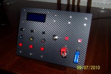
I'm gonna start this thread off with some details of my latest atempt at a button box :cool:. 100_1073.jpgI made this stand alone panel out of some 3mm perspex sheet, it utilises a Leo Bodnar BU0836 USB 'joystick' controller to connect the buttons and rotary encoders to the PC. Once all the holes were drilled, the panel was trimmed with a 3M made Dry Carbon look Vynil. Its suprisingly realistic and looks even better than it does in the pics!:cool:
All the switches are readily avilable from E-bay as is the 20x4 LCD panel and not as expensive as you might at first think!
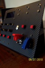
100_1075.jpg Its suprising how helpful it is not having to look for buttons on the keyboard mid race as the switches on the button box fall to hand much easier! If enough people ask, I will write a comprehensive tutorial
 
Ok this is final question as ive ordered all of my parts and extras now but would it be possible to mount the Kintters on the other side, poking though the front rather than placed on the front (if you undertand) like;
button.png

So as that they will not stick out too much

Ta,
Dan.
 
Upvote 0
Ok this is final question as ive ordered all of my parts and extras now but would it be possible to mount the Kintters on the other side, poking though the front rather than placed on the front (if you undertand) like;
button.png

So as that they will not stick out too much

Ta,
Dan.

Only way I can think to do it would be to glue a second piece of perspex to the back of the first and mount the button on the second piece of perspex.
 
Upvote 0
Neil is right there, but to be honest, it would look mesy as the metal button shrouds on the knitters is tapered (You will see when you get em)
I did think the same when I saw them, but actually, on the wheel, they look right, and the quality of them shows right off if you just mount them normally!
 
Upvote 0
Another quick question Brian. How would I go about mounting the SLI-Pro to the perspex? Oh, and I'm off on hols for two weeks tomorrow, so if I'm not around I'm not deserting the forum lol. Be excited to see how much progress others have made when I get back and then I'll be ordering all the gubbins.
 
Upvote 0
Two ways really, first one is to use a clear or light tinted perspex and mount it behind so its leds shine through, or better, use a template (I can send you one) and cut/drill holes in the perspex for the gear ind/led's

Enjoy your Hols :)
 
Upvote 0
Two ways really, first one is to use a clear or light tinted perspex and mount it behind so its leds shine through, or better, use a template (I can send you one) and cut/drill holes in the perspex for the gear ind/led's

Enjoy your Hols :)

The first way you suggest is what I was going to do but would be grateful for the template. And I worded my question incorrectly. Should have said, how would I go about fixing it to the perspex?
 
Upvote 0
Just drill four small holes to match the holes for mounting the SLI-M (look at pics of SLI you will notice em) and use small allen head bolts, have a few washers to hand to space it out so the LED's dont touch the perspex..........easy
 
Upvote 0
Im guessing that you stick carbon on perspex before you start cutting (if you have design like one I have)

Noooooooooooooooooooooooooooooooo Noooooooooooooooo Nooooooooooooo Nooo NO lol:tongue:

Thats the LAST thing you do. only put the carbon film on at the end, when your 100% happy with everything else. It trims easy with a scalpel or sharp hobby knife :):D
 
Upvote 0
Nice one Abdul:D

Take your time thinking about your layout! Think about the ergonimics of the panel, where and why a button/rotary should be in a certain position, make a cardboard dummy and try it out!

Good luck and have fun! :cool:
 
Upvote 0
:O cant believe how fast I got my parts. Ordered everything at about 3PM GMT yesterday and today I come home from work and 3 parcels are waiting on the floor! :D Got everything apart from SLI-M, Carbon and Rotary Knobs. Super fast delivery by all suppliers you recommended.

Oh and Brian I see what you mean about those Rotaries, even though I havnt got the knobs on yet I can tell that they will be very firm :D Great. Woo Sooooooo excited :D :D :D

Edit: Thanks about the carbon, see if I didnt ask all these millions of questions it all would have gone wrong lol
 
Upvote 0
Just cut off the end that does not fit the board:), the MIDDLE wire MUST go to the MIDDLE tag on the rotary, then the two OUTTER wires to the OUTTER tags (This is IMPORTANT lol) Use one cable per rotary and fit cable to board so it covers BTN1-GND-BTN2 for the first rotary then BTN3-GND-BTN4 for then next one:D

Knitters are simple, they have 3 Tags, IGNORE the middle one, use one outter as GND one as BTN. You can wire TWO knitters to one cable, just share the GND..........I.E. one side of the knitter goes to the middle wire (GND) the other to BTN5, the next knitter, one side goes to the same middle wire (GND) (just make a jumper wire from an off-cut) the other side to BTN6

Easy, any questions, if not go get that soldering iorn HOT lol!:D

ASK IF YOUR NOT SURE!:tongue:

EDIT: IMPORTANT this is for the SLI-M shift light, NOT the button box, tho that are similar, there are a number of ways to wire, I will cover this in the next TUT
 
Upvote 0
I will make one with a standard controller as basics.
Got everything here, but still need to find out how some wires need to go and where I need to cut the lines on the silicon plate. The wires are soldered on the print, but some buttons are standard 'on' while others work correctly. At those not wrking correctly I need to find out where to cut some lines.

PS the controller was only €4 and has 12 buttons + POV available.
 
Upvote 0

Latest News

Are you buying car setups?

  • Yes

  • No


Results are only viewable after voting.
Back
Top